TRANSMISSION INSTALLATION
7C - 112
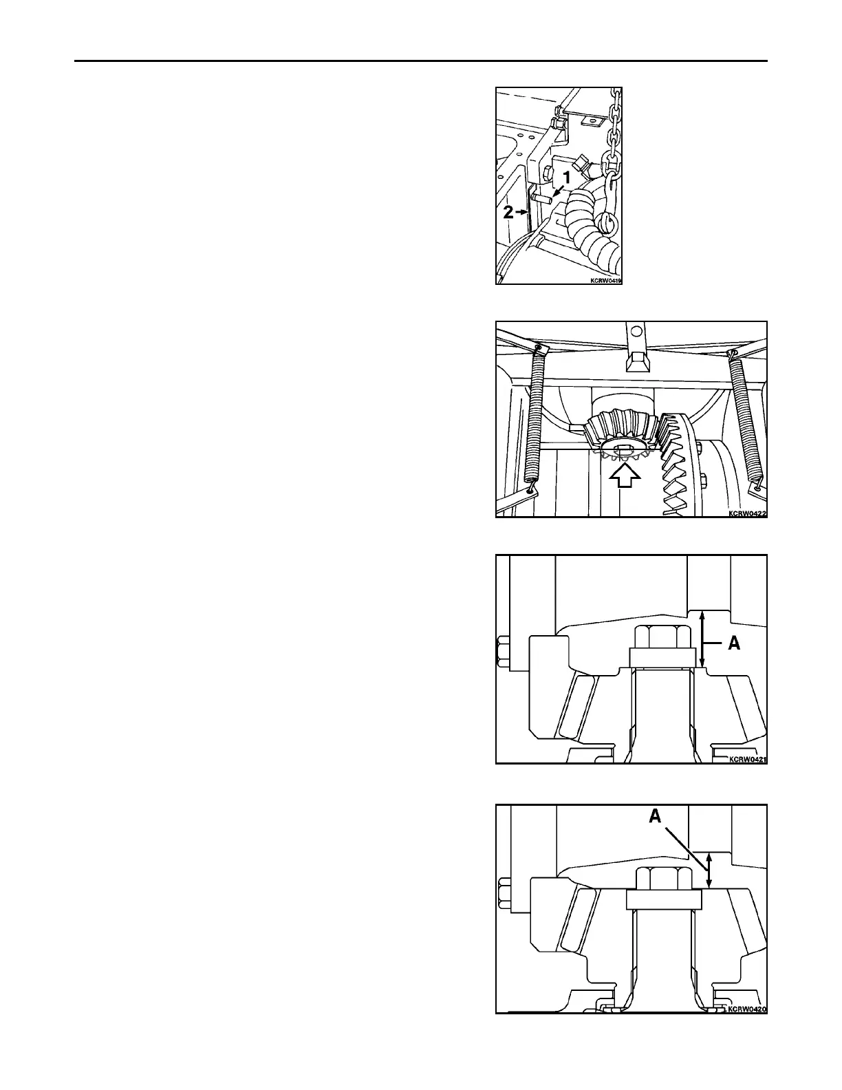
9. Install aligning studs (1), DR04-721-8, to top transmission
mounting bolt holes. Position five 0.5 mm (0.020 in) mounting
shims (2) on each stud. On pinion gear notate and record
dimension etched on face of gear. Coat new mounting o-ring
with liberal amount of amber grease. Using hoist position
transmission in place and work into rear main frame engaging
pinion gear with ring gear. Install mounting bolts and torque to
130 NCm (100 lbf ft).
10. Measure and record distance (A) between face of pinion gear to
ring gear carrier machined groove. Add or subtract mounting
shims to bring pinion gear within dimension etched on face,
recorded in Step 9, within 0.025 mm (0.001 in). Torque trans-
mission mounting bolts to 352 to 406 NCm (260 to 300 lbf ft).
11. D32E-1, D32P-1, D38E-1 or D38P-1
12. D39E-1 or D39P-1
.
 Loading...


