7E - 43
BEARING CARRIER STEERING DRIVE
SERVICE
REMARK
For removal of brake carrier, refer to DISASSEMBLY and follow
steps to brake carrier removal.
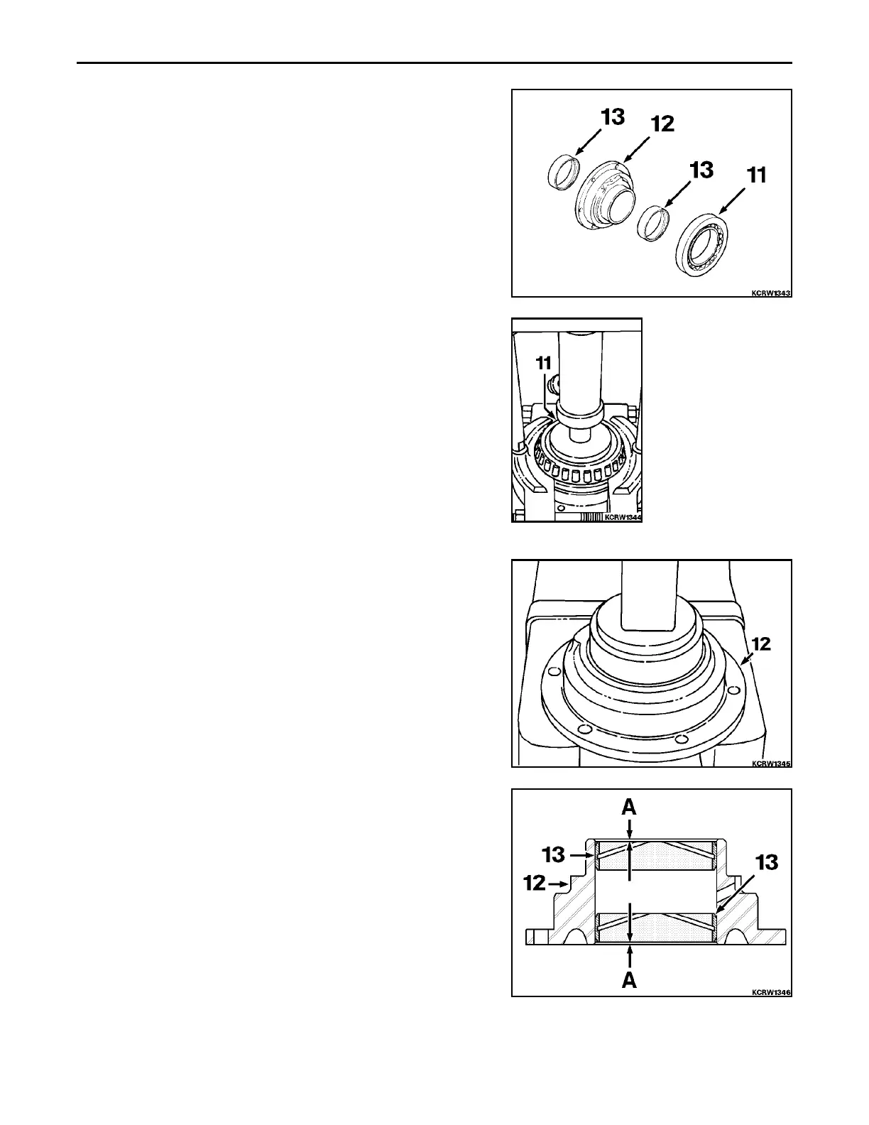
11. Tapered Roller Bearing
12. Bearing Carrier
13. Carrier Bushing
1. Install puller arrangement to bearing cone (11). Apply ram to
puller arrangement and unseat bearing cone.
2. Position bearing carrier (12) in press with opening under carrier
large enough so pressed out bushings will clear when removed.
Apply press and remove both bushing at same time.
A. 0.76 to 2.03 mm (0.03 to 0.08 in)
12. Bearing Carrier
13. Bearing Carrier Bushings
3. Install bushings (13) into bearing carrier (12) as follows.
 Loading...


