STEERING DRIVE BRAKE CYLINDER
7E - 28
REASSEMBLY
REMARK
Callouts from exploded and cross section views correspond with
callouts in following steps.
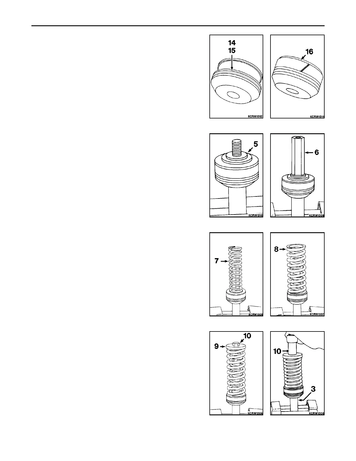
1. Install o-ring (15) in piston. For ease of assembly, soak piston
seal ring (14) in water heated to 82 to 93EC (180 to 200EF) until
it is pliable. Install heated seal ring into piston groove over inner
o-ring.
2. Install wear ring (16) to piston.
3. Install piston (5) to rod.
4. Install connecting nut (6) tight to piston rod.
5. Install inner spring (7).
6. Install outer spring (8).
7. Install retainer plate (9) and bolt (10).
8. Compress springs with retainer bolt (10). Insert bolt down until
contact with piston rod is felt.
 Loading...


