12 - 28
POWER THROTTLE
ADJUSTMENT
Adjust brake and decelerator pedal (1) to the specified height. Adjust
bolt (2) so that threaded tab (3) of throttle control bellcrank is
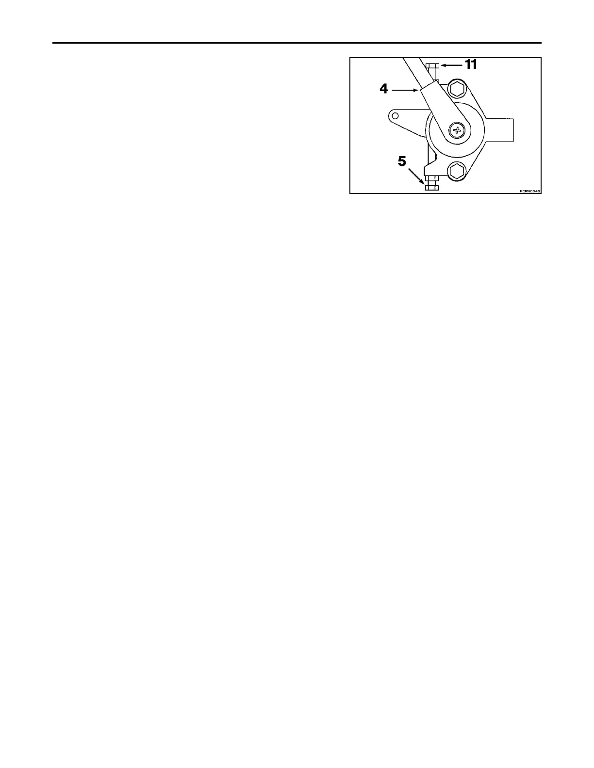
vertical. Place throttle lever (4) in detented LOW IDLE position.
Adjust stop bolt (5) so that it just contacts throttle lever and lock in
place. Adjust the length of the throttle rod (6) to fit between the
center of the slot (7) of the throttle control bellcrank (8) and the
injection pump lever (9) held against its LOW IDLE stop. Tighten the
bolt (10) so that throttle rod is in the center of the slot.
Move the throttle lever (4) toward the HIGH IDLE position until the
injection pump lever (9) contacts high stop on the pump. Adjust stop
bolt (11) on throttle lever and lock in place. With throttle lever in
HIGH IDLE position, back off stop bolt (2) until contact with pickup
tab (12) is just being made. Lock bolt in place. Make sure the
transmission is in neutral. Start engine and depress brake and
decelerator pedal until decelerated speed is obtained, 800 to 900
rpm. Adjust bolt (13) to contact stop block when decelerated speed
is reached.
1. Brake and Decelerator Pedal
2. Adjustment Bolt
3. Threaded Tab
4. Throttle Lever
5. Low Idle Stop Bolt
6. Injector Rod
7. Center of Slot
8. Throttle Control Bellcrank
9. Engine Injector Lever
10. Injector Rod Bolt
11. High Idle Stop Bolt
12. Bellcrank Pickup Tab
13. Decelerator Stop Block Bolt
 Loading...


