REASSEMBLY FINAL DRIVE
7F - 17
D32E-1, D32P-1, D38E-1 OR D38P-1
REMARK
Callouts from exploded view correspond with callouts in following
steps
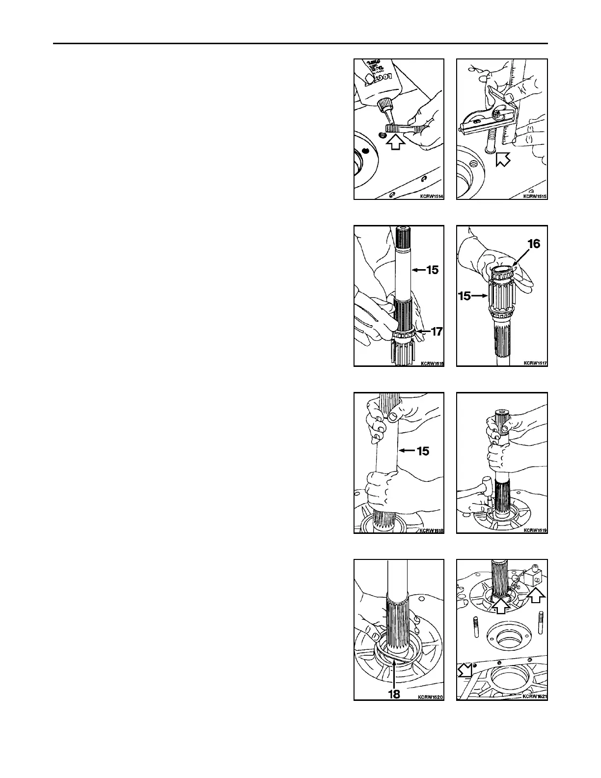
1. Block final drive housing in a horizontal position with rear main
frame mating face up. Check height of two mounting studs for
65 mm (2.56 in) dimension. If necessary to install new studs,
use Loctite #568 or Plastic Gasket.
2. Assemble studs to housing and set to 65 mm (2.56 in) dimen-
sion. If necessary, assemble drive pinion outer bearing cup (16)
into housing. Using a driver, tap to seat in housing.
3. Heat drive pinion inner bearing (17) to 135EC (275EF) for 45
minutes and assemble to shaft (15). Tap to seat against
shoulder of shaft.
4. Heat drive pinion outer bearing (16) to 135EC (275EF) for 45
minutes and assemble to shaft (15). Tap to seat against
shoulder of shaft.
5. Prelube drive pinion bearings and set shaft (15) into outer
bearing cone.
6. Using driver, install inner bearing cup until a slight resistance to
rotation is felt.
7. Attempt to insert 2.769 mm (0.109 in) retaining ring (18). If
possible to insert ring, bump cup back against ring with slide
hammer. If shaft rotates freely assembly is complete.
8. Position indicator against hose clamp assembled to shaft. Set to
zero. Insert pry bar between housing and shaft. Pry shaft
upward from within housing to determine end play. Observe and
record reading. Repeat two or three times and average read-
ings. Required end play is 0 to 0.229 mm (0 to 0.009 in). If end
play should exceed 0.229 mm (0.009 in) with 2.769 mm (0.109
in) retaining ring, install 2.972 mm (0.117 in) ring and bump cup
back against ring. If 2.769 mm (0.109 in) retaining ring will not
fit, or shaft will not rotate freely, install 2.565 mm (0.101 in)
retaining ring and bump cup back against retaining ring.
 Loading...


