TRANSMISSION TRANSMISSION/STEERING VALVE
7C - 134
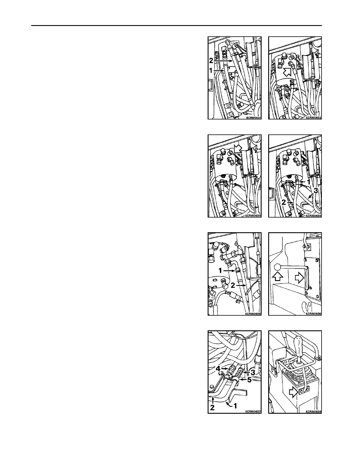
5. Remove trans/steer valve inlet (1) and outlet (2) hoses.
REMARK
Tag, cap and plug all disconnected hoses, tubing and fittings.
6. Disconnect 1st speed hose from fitting at side of trans/steer
valve.
7. Disconnect wires at back up alarm switch.
8. Disconnect reverse (1), forward (2) and 2nd speed (3) hoses
from fittings at bottom of trans/steer valve.
9. Disconnect steering right brake (1) and clutch (2) hoses from
fittings at side of trans/steer valve.
10. Remove ball knob from safety lock lever. Remove hardware
and slide front cover off lever.
11. Disconnect left brake (1) and clutch (2) tubes from hoses (3 and
4) at bottom of battery box. Unclamp (5) tubes. Remove clutch
tube first, then brake tube from fittings at side of transmis-
sion/steering valve.
REMARK
Left brake and clutch tubes have a M23 hex nut at valve fittings.
12. Remove feathering handle.
 Loading...


