SPLIT LINK TYPE CHAINS TRACK CHAIN
15 - 7
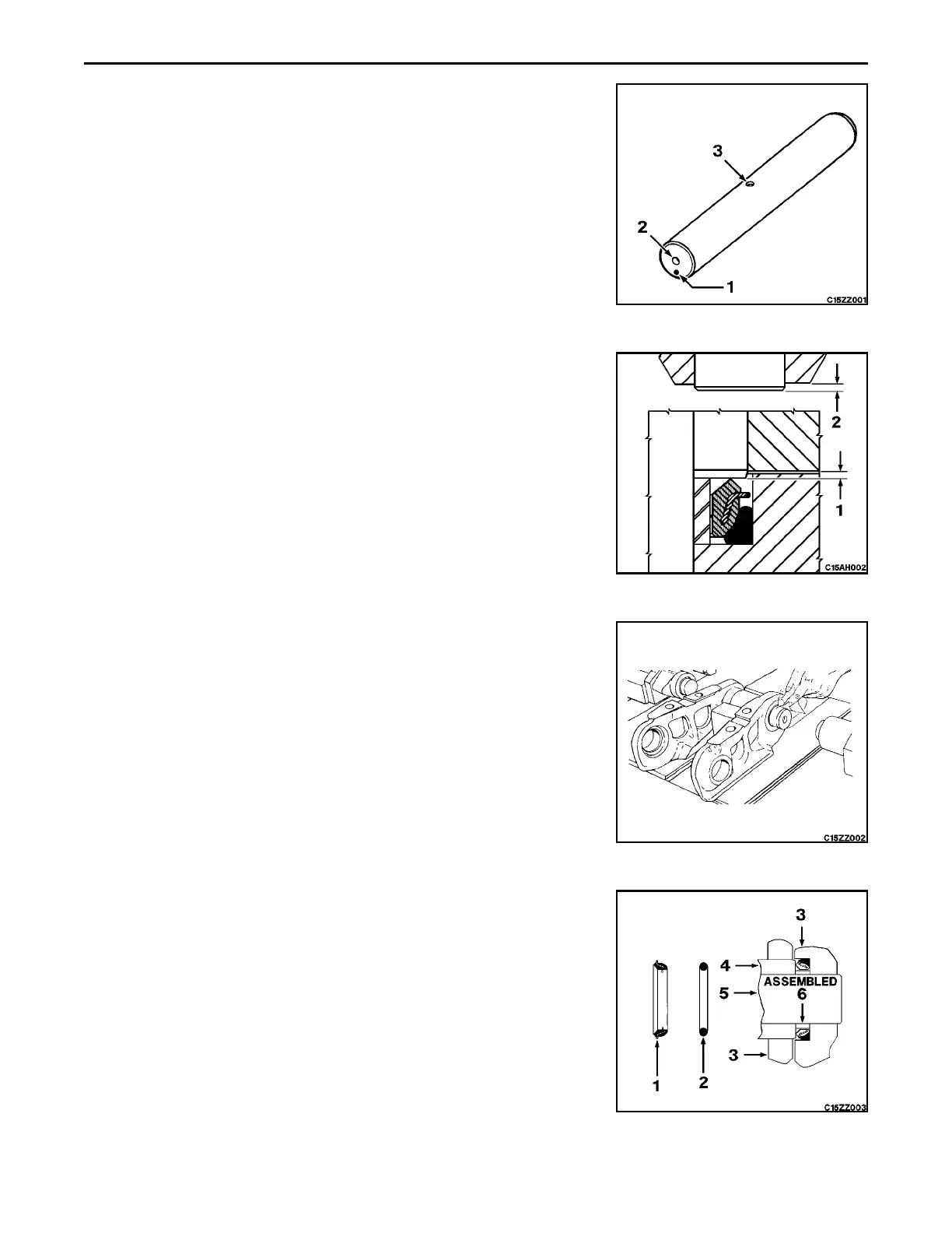
Reassembly
1. On new or reused pins, index a mark (1) on hole end (2) of pins on
opposite side of lube hole (3).
2. Adjust press to above specified force. Install assembly adapters on ram
heads. Bolt split links together and position on press assembly adapters.
Position a bushing in press saddle. Press links onto bushing to projection
height (1) specified. Remove bolts securing two halves together.
3. Advance chain on press and position a pin in assembled bushing. Apply
a coat of oil on ends of bushing with tissue (not your fingers) being
careful not to get it on pin surface. Position next bushing in press saddle.
4. Install o-rings (2), seals (1) and spacers (6) in counterbore of next chain
links. Apply Loctite #680 sparingly in outer half of pin bore of links.
Position links on press assembly adapters. Check that index mark is at
bottom. All lube holes must face same direction. Press links onto pins
and bushings being sure that link counterbore and bushing face are
seated against spacer. Do not exceed force indicated as this can
damage spacer. Do not adjust links for bolt hole location. After chain is
moved to next position, place a rubber plug in end of pin of completed
joint. Tap it in until it is flush or slightly below chamfer of pin hole.
 Loading...


