2G6
2-3-3
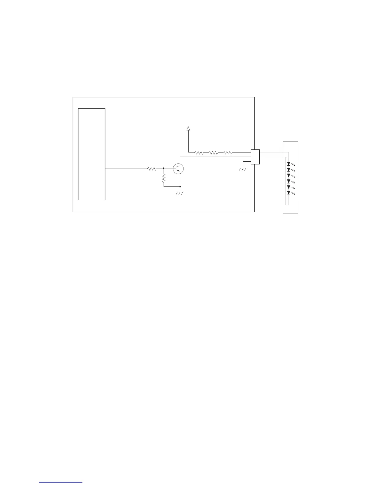
(1) Eraser lamp control circuit
The CPU (U1) turns pin #23 (ERASER) of U1 to H level, transistors (Q14) turns on consequently, and the 24 V DC given at
pin #1 of connector YC5 applies to the eraser lamps. The eraser lamps thus illuminate as the current flows through the
resistors (R109, R110, and R111), eraser lamp, the pin #2 of connector YC5, transistor Q14 and the ground.
GND
PGND
1
2
3
2
3
1
Q14
R69 R70 R71
ERASER
+24V3
YC14
ERASPW
Eraser lamp
P25/ASCK0
23
CPU
U1
ERASER
Engine PWB
Eraser lamp control circuit
Figure 2-3-3 Eraser lamp control circuit

 Loading...