2G6
2-3-12
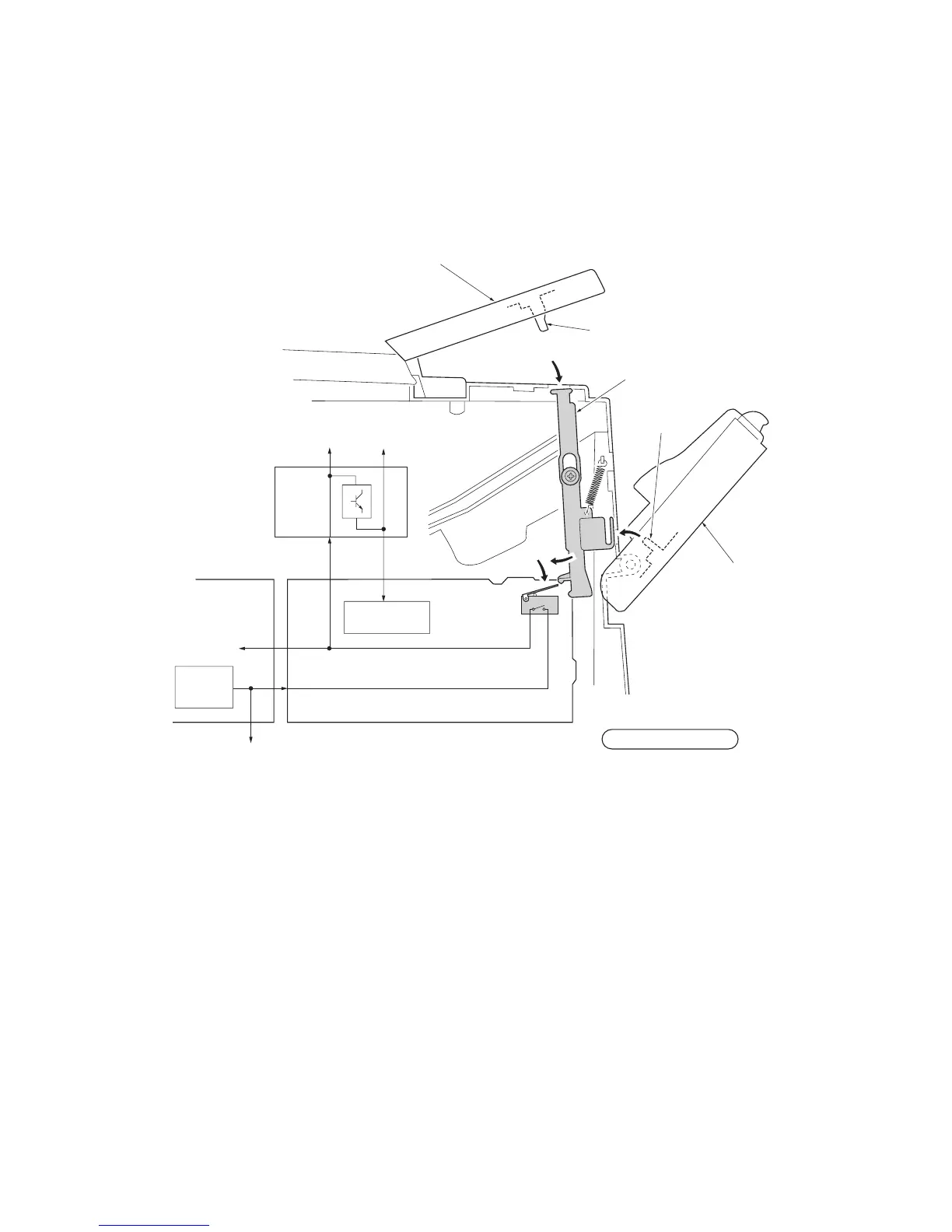
(1) Interlock switch
The interlock switch is located on the high voltage unit and opened and closed in conjunction with the front cover or the top
cover via the interlock lever. This switch connects and disconnects the +24 V DC power supply line. If the front cover or the
top cover is open, the interlock switch is open, and the +24 V DC to the high voltage output circuit, bias PWB, engine PWB,
and the power supply unit is disconnected, deactivating the high voltage output, laser output, main motor output for safety.
The cooling fan is an exception: Since the cooling fan is directly fed with +24 V DC from the power supply unit at the primary
side (+24V1) of the interlock switch, the cooling fan is not deactivated even the cover is open.
High voltage unit
Power supply unit
Interlock
switch
Interlock lever
Projection
Projection
Top cover
Machine left side view
+24V1+24V1
+24V2
+24 V DC
output
+24V2
+24V3
+24V2
High voltage
output circuit
Bias
PWB
Cooling fan
Triac, etc.
Front cove

 Loading...