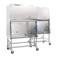
Avoid cabinet locations that require an elbow
directly above the cabinet’s exhaust connection
or an excessive number of elbows in the exhaust
system. There should be a straight length 10
duct diameters long between the cabinet
connection and any elbow, and between
subsequent elbows. See Figure 7-2.
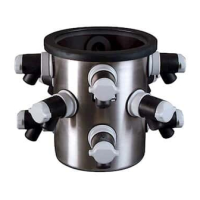
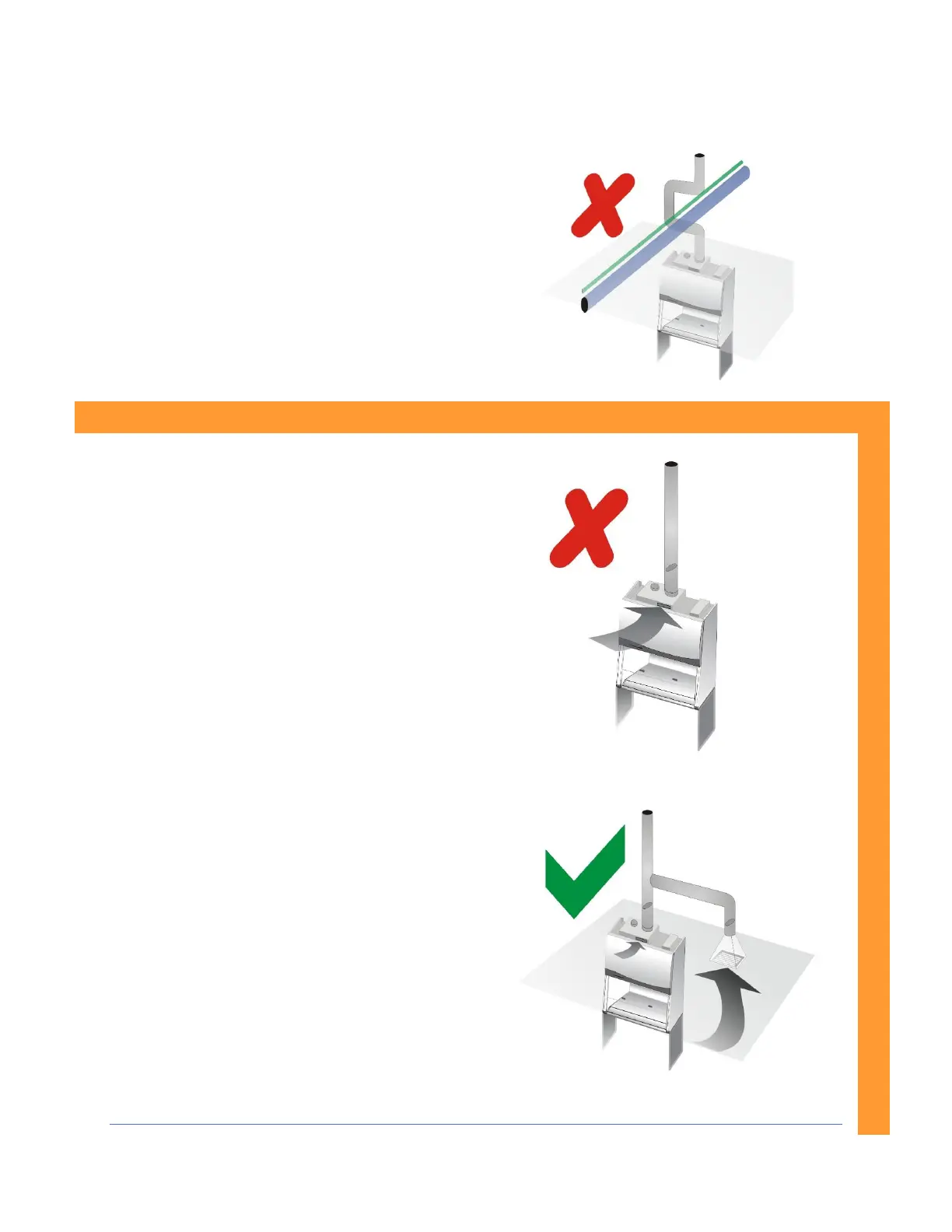
The Inlet Relief Valve located on the top of the
cabinet is designed to draw a maximum of 100
CFM (170 m
3
/hr).
Attempting to draw additional room air through
the valve (room air exhaust), can result in
unstable cabinet operation. See Figure 7-3.
If additional room exhaust needs to be drawn
through the exhaust system, install an additional
duct and balancing damper downstream of the
cabinet’s damper. This will allow for proper
balancing of the system. See Figure 7-4.
This information applies to Canopy-Exhausted Type A2 and C1 (in B-Mode) only