88
Ground Fault Circuit Interrupter (GFCI) Test
To test the biosafety cabinet’s internal GFCI outlets, follow these instructions:
This test may only be applied on 100-115v models. 208-230v models do not contain
GFCI outlets internal to the biosafety cabinet.
Note: The GFCI tester must be capable of simulating a fault of 3mA.
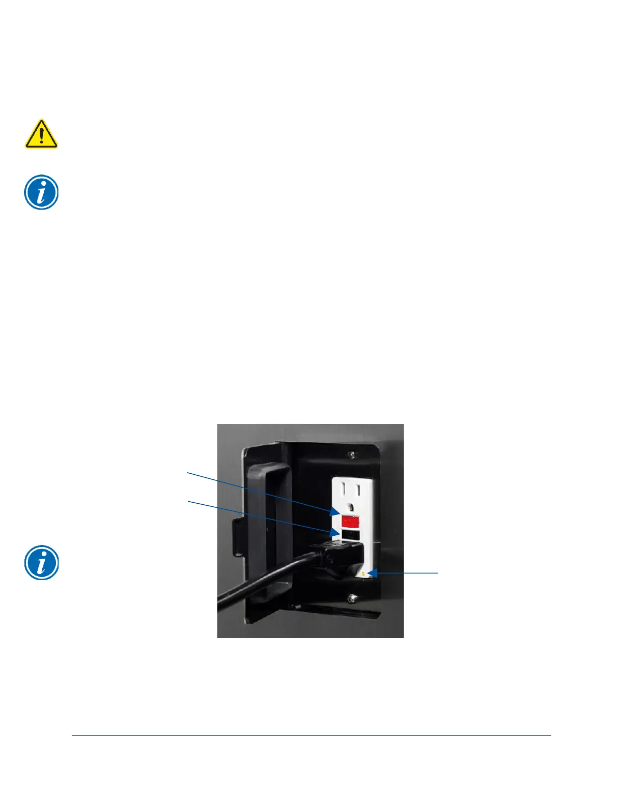
1. Place the tester into any of the biosafety cabinet’s outlets. The left side outlet is
a standard (non-GFCI) outlet, but it is wired to the LOAD side of the GFCI outlet
on the right side wall. It will respond the same; however, to reset power to the
outlets after the test, the Reset Button on the right side outlet needs to be
pressed.
2. Press the test button on the GFCI tester. The indicator lights on the tester should
indicate the outlet is inactive, and the GFCI outlet’s power indicator LED should
be off. See Figure 10-35 for reference.
3. Reset the GCI by pressing the RESET button on the right side outlet. The tester
should indicate power is correctly present at the outlet, and the GFCI outlet’s
power indicator LED should be on.
Acceptance Criteria
The GFCI tester and GFCI outlet in the biosafety cabinet respond as indicated in steps
2 and 3.