168
Exhaust Damper Installation Procedure
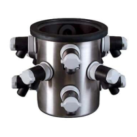
The air-tight damper shown is not supplied with the canopy kit. Proper installation of the
canopy’s damper is crucial for correct alarm system operation. If you have questions,
please call Labconco’s Product Service Department. Labconco offers an optional gas-
tight exhaust damper (Catalog Number 3776800). An equivalent 10-inch OD damper
can be used if desired.
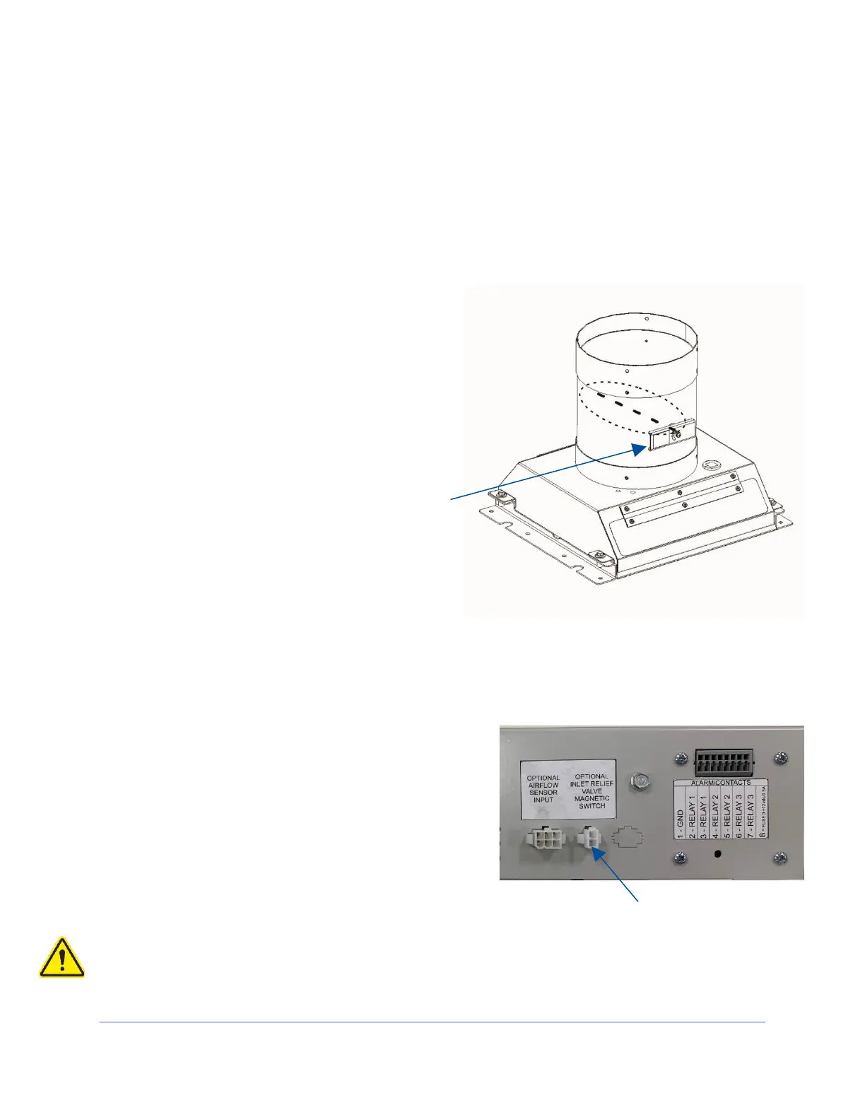
1. Install the damper on top of the
canopy, ensuring that the control lever
faces the front of the unit as shown in
Figure 17-5.
2. Use a proper silicone sealant (not
supplied) and the screws supplied with
the air-tight damper to seal the damper
to the canopy.
Canopy Switch Wiring Connection
1. Ensure that the cabinet is unplugged.
2. Connect the canopy connector to the two
pin connector located on the left side of the
electronics module (see Figure 17-6).
Ensure there is slack in the sensor cable
where it connects to the harness, and it
does not impede the operation of the intake
valve.
Ensure the sensor harness does not contact any moving parts.