175
5. Run the cable and its connector through the sheetmetal hole for the sealing
grommet. Make any final adjustments to the location of the sealing grommet and
replacement plug on the airflow sensor cable. Press the sealing grommet into
the sheetmetal hole from the top of the canopy or exhaust housing.
Connection to Electronics Module
After installation, follow these steps to connect the airflow sensor to the biosafety
cabinet’s electronics module.
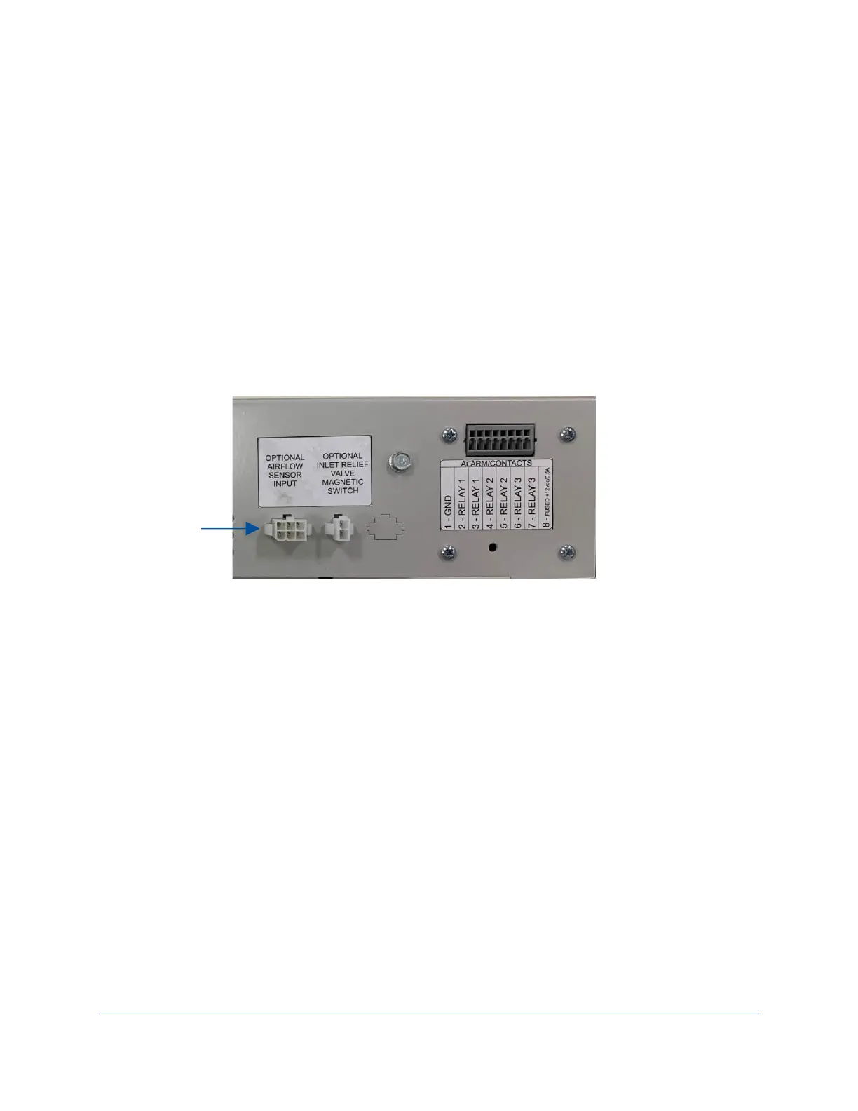
1. Identify the “Optional Airflow Sensor Input” label on the left side of the biosafety
cabinet’s electronics module. See Figure 18-8.
2. Connect the airflow sensor cable to this connector on the electronics module.
3. Tidy up excess length of cable from the airflow sensor by creating a few loops if
necessary, and zip tie the loops. Secure the cable to the top, front lip of the
biosafety cabinet with zip ties to ensure it does not interfere with the sash pulley
axle.
4. Reconnect the biosafety cabinet to electrical power.