144
Display Board
The LCD display and circuit board assembly contain the microprocessor which controls
all functions of the biosafety cabinet. The data ribbon cable, keypad cable, and speaker
cable all connect to the display board. To replace the display board, follow these
instructions.
1. Open the right side panel as described in Removal of External Dress Panels in
Section 13.
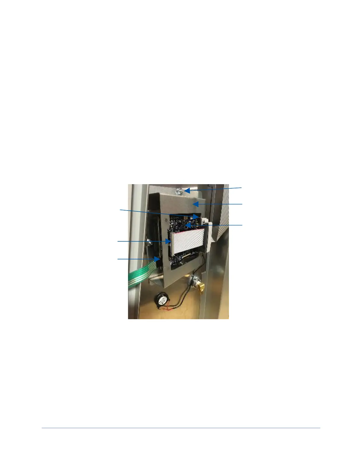
2. Disconnect the three wire connections to the display board, see Figures 13-4 and
13-5 for reference. Note: Speaker connector easier to remove after Step 3.
3. Using a 3/8-inch socket or nut driver, remove the two nuts securing the display
bracket. See Figure 13-4 for reference. The display board is attached to the
display bracket, and will come with the display bracket. Remove the display
bracket.
4. Using a #2 Phillips screwdriver, remove the four (4) screws holding the display
board to the display bracket.
Reinstallation Notes:
1. When reconnecting the keypad connector to the display board, it can be
assembled correctly or backwards. The correct orientation is for the visible silver
connectors on one side of the keypad connector to face away from the LCD
display screen on the display board. See Figure 13-5 for reference.