DC-bus c
onnecon
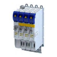
The inverters are designed for DC-bus connecon with a central AC system feed-in point.
Suppliers with various services are available for this purpose.
Parallel operaon of suppliers to increase supply power or braking power is permied.
Advantages of a DC-bus connecon
•
Ener
gy exchange between the inverters in motor operaon and in generator operaon.
•
Reduced supply power from the AC system
•
Design of the supply modules with lower rated power
•
Reduced braking losses in regenerave operaon
•
Only one AC mains connecon
•
Reduced wiring eort due to integrated busbar system
Important notes
The inverters in the network may only start oper
aon when the DC bus is fully charged. This
means that all inverters in the network must be supplied with 24 V.
NOTICE
The 24 V supply is not switched on for all inverters in the DC bus.
P
ossible consequences: Charging relay or charging hybrid can be destroyed.
▶
Feed all inverters in the DC-bus connecon via a common and stable 24 V supply.
▶
With split 24 V supply and fuse protecon: If a fuse responds, shut down the enre drive
train if possible to avoid cyclical voltage strokes in the DC bus.
Precondions f
or trouble-free DC-bus operaon
•
The r
ated values of the mains voltage or the DC bus voltage must be the same for all
inverters in the network.
•
The total DC power P
DC
must be provided by the supplier. 4Dimensioning ^ 43
•
The busbar system must not be overloaded:
•
Max. connuous current: 120 A.
•
Max. overload: 180 A for 60 s.
•
Unloading phase aer overload: Max. 90 A for 120 s.
•
Braking operaon with suppliers connected in parallel:
•
The switching thresholds of the brake choppers must be set to the same value.
•
The control of the brake chopper must be synchronized by master-slave connecon.
4Braking operaon ^ 39
Informaon on pr
oject planning
DC-bus connecon
Important notes
35

 Loading...