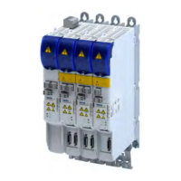
Motor cable
EMC-compliant ins
tallaon must be carried out with shielded low-capacitance motor cables.
Capacitance per unit length
•
Cable cr
oss-secon ≤ 2.5 mm² (≥ AWG 14): C-core-core/C-core-shield <75/150 pF/m
•
Cable cross-secon ≤ 4 mm² (≥ AWG 12): C-core-core/C-core-shield <150/300 pF/m
Braid
•
Only use motor cables with braids made of nned or nickel-plated copper.
•
Shields made of steel braids are not suitable.
•
The overlap rate of the braid must be at least 70 % with an overlap angle of 90 °.
Cable for motor temperature monitoring
•
Shield the cable for motor temperature monitoring (PTC or thermal contact) and install it
separately from the motor cable.
•
In Lenze system cables, the cable for the brake control is integrated into the motor cable. If
this cable is not required, it can also be used to connect the motor temperature
monitoring up to a length of 50 m.
Measures on the motor
•
Connect the shield with PE over a large area at the terminal box of the motor, e.g. via a
metallic EMC cable gland.
•
For motors with plug connectors, the large-area shield connecon is ensured via the plug
connecon.
Further supporng measur
es
•
R
oute the motor cable separately from the mains cables and control cables.
•
Lay the motor cable so that it only crosses mains cables and control cables at right angles.
•
Do not disconnect the motor cable.
•
If the motor cable must be disconnected (e.g. by chokes, contactors, or terminals):
•
Install the shield of the motor cable directly before and behind the point of separaon
to the mounng plate with a large surface.
•
The unshielded cable ends must not be longer than 100 mm.
•
Mount the separang component at least 100 mm away from other components.
Control cables
•
Install the cables so that no inducon-sensive loops arise.
•
Distance of shield connecons of control cables to shield connecons of motor cables and
DC cables:
-
At least 50 mm
•
Control cables for analog signals:
-
Must always be shielded
-
Connect the shield on one side of the inverter
•
Control cables for digital signals:
Cable length
< ca. 5 m ca. 5 m ... ca. 30 m > ca. 30 m
Type unshielded opon unshielded twisted opon always shielded
c
onnected on both sides
Electrical ins
tallaon
EMC-compliant installaon
Motor cable
52

 Loading...