Brake resistor c
onnecon
The brake resistor is connected to terminal X103 on the supplier.
Use intrinsically safe brake resistors to be able to dispense with a separate
s
witch-o device (e.g. a contactor).
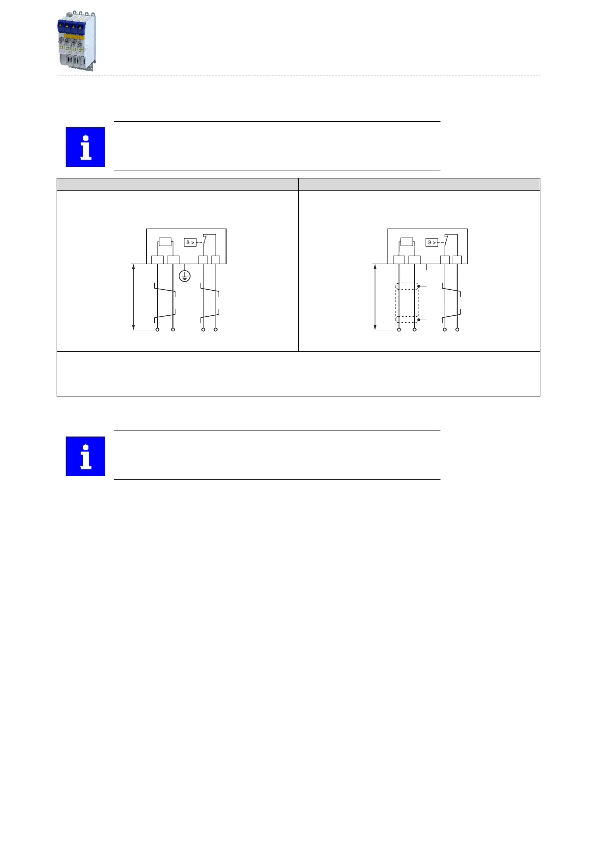
Short c
onnecon cables up to 0.5 m Long connecon cables up to max. 5 m
Up to a cable length of 0.5 m, the cable for the brake resistor and that of
the temperature monitoring can be twisted. Doing so reduces problems
due to EMC interference.
The cable of the brake resistor must be shielded.
The maximum length is 5 m.
Twisng is sucient for the temperature monitoring cable.
① Wiring to the "brake resistor" c
onnecon on the component with brake chopper.
② Oponal: Wiring to a control contact that is set to monitor the thermal contact.
If the thermal contact responds, the voltage supply to the component with brake chopper must be disconnected (e.g. switch o the control
of the mains contactor).
DC-bus c
onnecon
Detailed informaon on the DC-bus connecon can be found here: 4DC-bus
connecon
Electrical ins
tallaon
Brake resistor connecon
65

 Loading...


