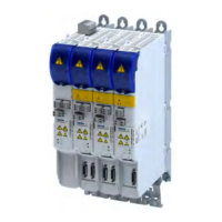
Electrical isolaon
Ensure a trouble-free oper
aon:
Carry out the total wiring so that the separaon of the separate potenal areas
is preserved.
Supplier Inverter
X103
X20.1
X20.2
X21
X100
X101
X102
X109X105
X107
X106
X3
X1
X236 IN
X237 OUT
X5
X8
X7
X101
Legend
Hazardous mains potenal (No insulaon)
Simply isolated from the mains pot
enal (isolaon by basic insulaon)
Safely separated from the mains pot
enal (isolaon by double or reinforced insulaon)
Protecon against accidental contact is guaranteed without any further measures.
Isolaon b
y funconal insulaon
X100 L1, L2, L3, PE Mains c
onnecon X101 +UG, -UG DC bus
X101 +UG DC bus X105 U, V, W, PE Motor connecon
X102 -UG DC bus X1 SIA, SIB, GS Basic Safety - STO (Opon)
X103 Rb1, Rb2, PE Brake resistor connecon X3 DI1, DI2, GDI Control terminals
X20.1 DI1, DI2, DI3 Digital inputs X5 24E, GE 24 V supply for control electronics
X20.2 DO1, DO2, GD Digital outputs X236 IN RJ45 onboard EtherCAT IN
X21 24E, GE 24 V supply for control electronics X237 OUT RJ45 onboard EtherCAT OUT
X7 Sub-D, 9-pole Resolver connecon (opon)
X8 Sub-D, 15-pole Encoder connecon (opon)
X106 BD1, BD2 Motor holding brake connecon
X107 24B, GB 24 V supply for motor holding brake
X109 T1, T2 HIPERFACE DSL® (OCT) (opon)
Electrical ins
tallaon
Important notes
Electrical isolaon
49

 Loading...