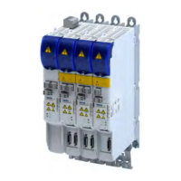
DC-bus with power supplies operated in parallel
Suppliers can be operated in parallel to increase DC supply power and/or increase braking
po
wer.
The suppliers operated in parallel are connected to the AC mains via an RFI lter or a mains
lter.
Parallel oper
aon of suppliers is not permied in UL-approved facilies.
M M M M
...
G1
V2
Gx
L1
L3
L2
...
Z21
V1
L1
L3
L2
AC
Z2
3
Z20
L1
L3
L2
L1
L3
L2
AC
Z1
3
V2V1
Fig. 3: Basic circuit diagram: DC-bus c
onnecon with suppliers connected in parallel
Z1 Mains lter
Z2 RFI lter
Z20,
Z21
Mains choke
V1, V2 Supplier
G1...
Gx
Inverter
Typical combinaons
Supplier Mains-side components DC output current
I
DC 100%
[A]
DC-supply power
P
DC 100%
[kW]
Collecve lt
er Mains choke
Mains lter RFI lter
400 V 480 V
E70ACPSx0304x
− E94AZRP0824
EZAELN3025B122
46.3 55.5
E70ACPSx0604x EZAELN3050B591
E70ACPSx0304x
E94AZMP0824 − −
46.3 55.5
E70ACPSx0604x
E70ACPSx0604x
− E94AZRP0824
EZAELN3050B591
51.5 61.7
E70ACPSx0604x EZAELN3050B591
E70ACPSx0604x
E94AZMP0824 − −
51.5 61.7
E70ACPSx0604x
E70ACPSx0604x
− E94AZRP2004
EZAELN3050B591
61.8 74
E70ACPSx0604x EZAELN3050B591
E70ACPSx0604x
E94AZMP2004 − −
61.8 74
E70ACPSx0604x
Informaon on pr
oject planning
DC-bus connecon
DC-bus with power supplies operated in parallel
37

 Loading...