Installation Guide
Installation of the Logipix Full HD Box camera
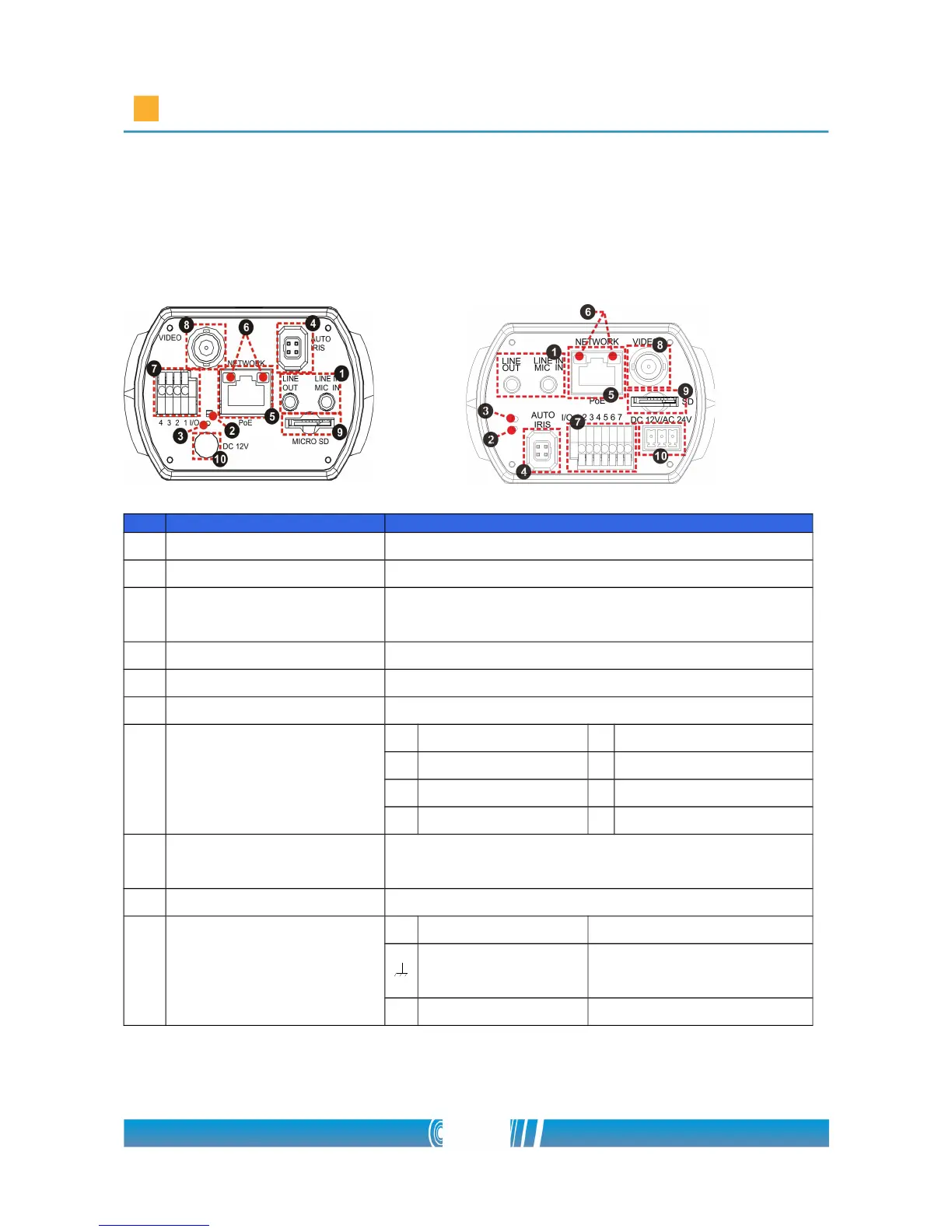
Camera Rear Panel
DC 12V / PoE DC 12V/ AC 24V/ PoE
No. Connector Definition
1 LINE OUT & LINE IN Two-way audio transmission
2 Power LED Power connection indication (green light)
3 Default button
Reset to factory default; press the button with
a proper tool
4 AUTO IRIS Connector Connecting to Auto Iris Lens
5 PoE NETWORK For Ethernet Cable and SPE connection
6 Network LEDs Network connection and activity indication
7 Alarm I/O
1 Output + 5 GND
2 Output − 6 D −
3 Input + 7 D +
4 Input −
8
VIDEO (BNC
connector)
For video output
9 Micro SD Card slot For videos and snapshots storage
10
AC 24V/DC 12V
Connector
(AC 24V Model)
+ AC 24V: Power-1 DC 12V: Power