©Copyright MAC Instruments 2005. All Rights Reserved. MAC155 Rev. 12
Pg 19
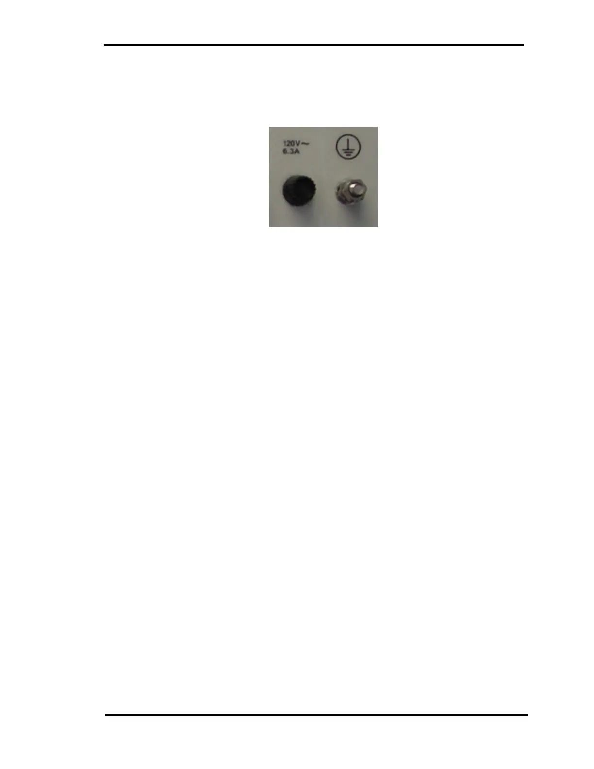
A grounding stud is provided on the back of the controller, this stud must be
connected to a suitable earth ground using at #12AWG / 4mm
2
or larger
grounding conductor.
Figure 12 – Controller PE / GND stud
CURRENT LOOP WIRING
The analog output signal (Current Loop) appears at a connector on the back
of the controller. A shielded twisted pair wire should be used to connect this
signal to a display or data logging system.
The current loop can be configured to 4mA–20mA or 0mA–20mA.
Configuration of the current loop is user selectable from the front panel of the
controller via a menu and pushbuttons. Refer to the Setup section for the
controller.
0 TO 10V OR 0 TO 5V OPERATION
The current loop configuration provides a high degree of immunity from
interference. To obtain a 0 to 5V or 0 to 10V signal, configure the current loop for
a 0 to 20mA output. Selection of the 0 to 20mA option is explained in detail in the
Controller Setup section. A voltage proportional to the output current can then be
obtained by connecting a 250Ω resistor for 0 to 5V signal or a 500 Ω for a 0 to
10V signal across the input terminals of the signal monitoring device.
The resistor is placed across the signal wires where the signal wires
terminate at the input of the monitoring device. A voltage will develop across the
resistor that is proportional to the output current of the MAC155.