214658 67 Revision A
Figure 5.29: Feeder House Lock
7. Measure the misalignment between pin (A) and feeder
house receptacle (B).
8. Lower header to the ground until the feeder house
disengages the top beam.
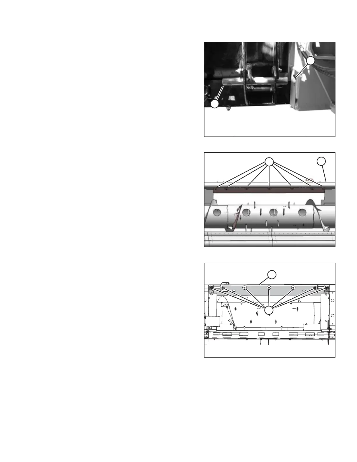
Figure 5.30: Top Beam (Front View)
9. Loosen the seven bolts (A) along top beam (B) on the
auger side of the header.
Figure 5.31: Top Beam (Rear View)
10. Loosen the seven bolts (A) along the top beam (B) on
the back side of the header.
ATTACHING HEADER TO COMBINE