IMPULSE•G+ Mini Advanced Instruction Manual - March 2014
3-6
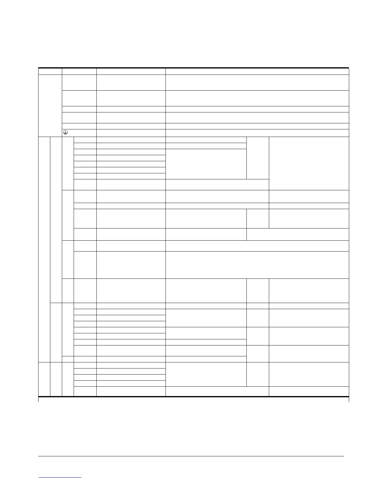
Terminal Description
Type Terminal Name Function (Signal Level)
Main Circuit
R/L1,
S/L2,
T/L3
AC power supply input AC power supply input
U/T1,
V/T2,
W/T3
Inverter output Inverter output
B1, B2 Braking resistor connection Braking resistor connection
+2, +1 DC reactor connection When connecting optional DC reactor, remove the main circuit short-circuit bar between +2
and +1.
+1, (–) DC power supply input DC power supply input (+1: positive; (–): negative)
Grounding Ground to local grounding codes
Control Circuit
Input
Sequence
S1 Multi-function input selection 1 FWD run when closed, stop when open H01.01 ~
H01.07
120VAC ±10%
S2 Multi-function input selection 2 REV run when closed, stop when open
S3 Multi-function input selection 3
Inputs are programmable
S4 Multi-function input selection 4
S5 Multi-function input selection 5
S6 Multi-function input selection 6
S7 Multi-function input selection 7
X2* Multi-function input selection
common
Common for control signal
Analog Input Signal
+V +10.5V DC
Power supply output
For analog command +10V power supply +10V (Allowable current 20 mA max)
A1 Master frequency reference 0 to +10V/0 to 100% 0 to +10V/(2K Ohm)
A2 Multi-function analog reference 4 to 20 mA/0 to 100%
0 to 10V/0 to 100%
0 to 20 mA/0 to 100%
H03.09 4 to 20 mA (250 Ohm), 0 to +10V/(2k
Ohm)
AC Frequency reference common 0V 0 to ±10V. Max ±5%
2mA or less
Safe Disable Input
HC Power Supply for safe disable
input
+24 VDC (max 10 mA allowed)
H1 Safe disable input Open: Output disabled
Closed: Normal Operation
NOTE: Disconnect wire jumper between HC and H1 when using the safe disable input. See
Safe Disable Function on page 3-7.
RP Pulse Input Pulse Input frequency reference H06.01 0 to 32kHz (3k impedance) ±5%
High level voltages 3.5 to 13.2
Low level voltages 0.0 to 0.8
Duty Cycle (on/off) 30% to 70%
Output
Multi-function
contact output
MP Pulse Monitor Pulse output frequency H06.06 0 to 32kHz ±5% output (load: 1.5k )
MA NO contact output
Factory setting: brake output
H02.01 Dry contact capability:
250VAC 1A or less,
30VDC 1A or less
MB NC contact output
MC Contact output common
P1 Photo coupler output 1
Outputs are programmable
H02.02 ~
H02.03
Photo-coupler output +48VDC, 50mA
or lessP2 Photo coupler output 2
PC Photo coupler output common 0V
AM
Analog monitor output Factory setting: output frequency 0 to
+10V
H04.01 +10VDC, 2mA or less, 8-bit resolution
AC Analog monitor common 0V
Communication
Circuit Terminal
MEMOBUS
communications
R+ Communications input (+)
MEMOBUS communication
Run through RS-485 or
RS-422.
H05.01 ~
H05.08
RS-485/422
MEMOBUS protocol, 115.2 kbps max.R- Communications input (-)
S+ Communications output (+)
S- Communications output (-)
I(G) Signal Common Connection to shield sheath of signal lead 0V
* Terminal X2 is only available on the AC option cards. Terminal SC is used with the DC terminal board.