SET-UP AND INSTALLATION RT9150E OPERATOR MANUAL
4-6
Published 2-23-2017, Control # 644-00
3. Make sure the live-loaded side (Figure 4-10) of the wire
rope is directly in line with the ears of the socket and the
direction of pull to which the wire rope will be subjected.
If the wire rope is loaded into the socket incorrectly,
under a load the wire rope will bend as it leaves the
socket, and the edge of the socket will wear into the wire
rope causing damage to the wire rope and eventual
failure.
4. Insert the end of a wire rope into the socket, form a loop
in the wire rope, and route the wire rope back through
the socket allowing the “dead” end (Figure 4-10) to
protrude from the socket. Ensure the dead end of the
wire rope is of sufficient length to apply end treatment to
the dead end after the wedge has been seated.
5. Insert the wedge into the loop and pull the live end of the
wire rope until the wedge and wire rope are snug inside
the socket. It is recommended that the wedge be seated
inside the socket to properly secure the wire rope by
using the crane’s hoist to first apply a light load to the live
line.
6. After final pin connections are made, increase the loads
gradually until the wedge is properly seated.
7. The wire rope and wedge must be properly secured
inside the socket before placing the crane into lifting
service. It is the wedge that secures the wire rope inside
the socket whereas the dead-end treatment is used to
restrain the wedge from becoming dislodged from the
socket should the wire rope suddenly become unloaded
from the headache ball or hook block striking the
ground, etc.
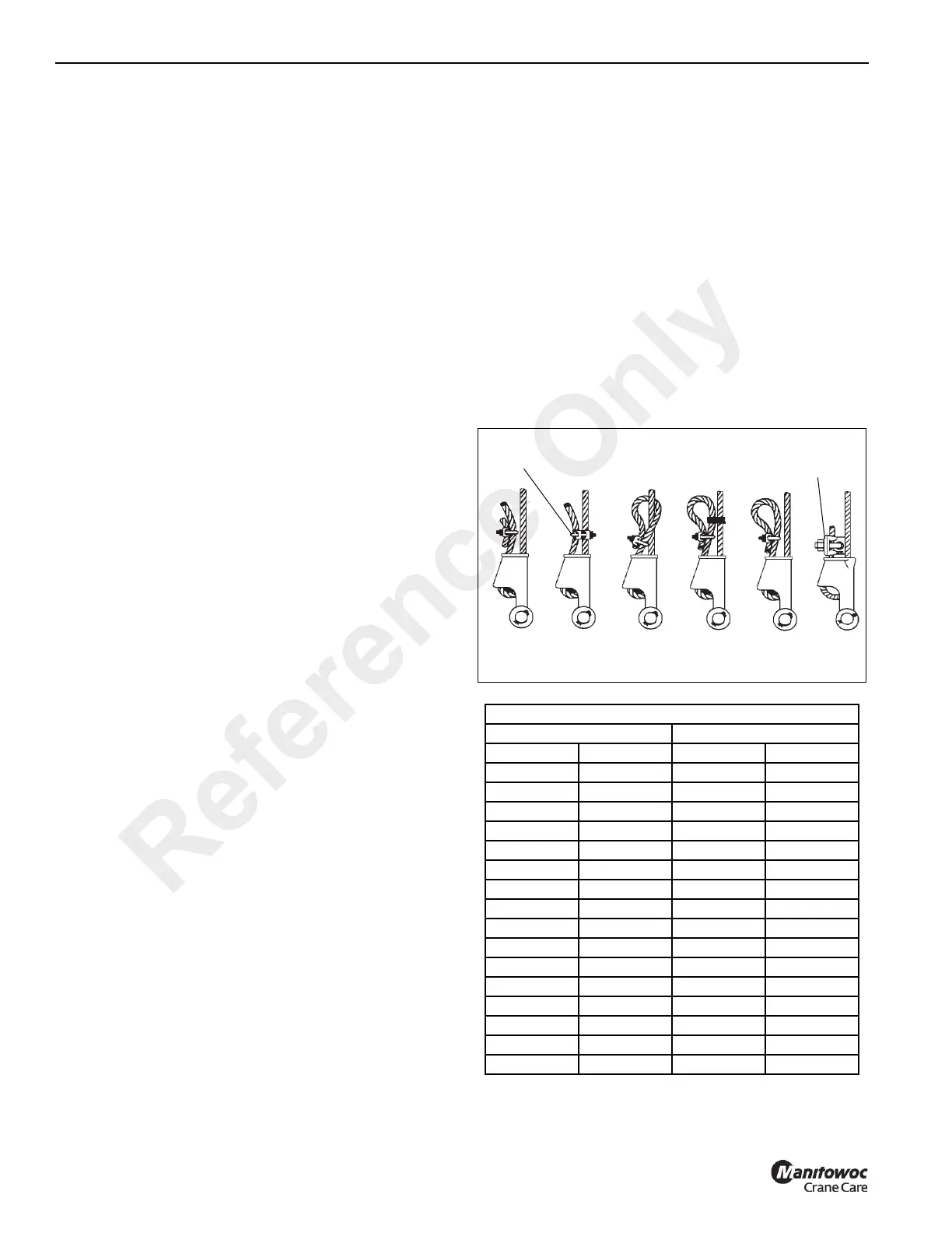
Sketches A through F (Figure 4-11) illustrate various
methods for treating the dead-ends of wire ropes which exit a
wedge socket assembly. While use of the loop-back method
is acceptable, care must be exercised to avoid the loop
becoming entangled with tree branches and other
components during crane transport and with the anti-two-
block system and other components during use of the crane.
Of the methods shown below, Manitowoc prefers that
method A or F be used on Grove cranes, i.e., clipping a short
piece of wire rope to the dead-end or using a commercially
available specialty wedge. Typically, it is recommended that
the tail length of the dead-end should be a minimum of 6 wire
rope diameters but not less that 6 in (15.2 cm) for standard 6
to 8 strand wire ropes and 20 wire rope diameters but not
less than 6 in (15.2 cm) for rotation resistant wire ropes.
When using method A, place a wire rope clip around the
dead end by clamping a short extra piece of wire rope to the
wire rope dead end. DO NOT CLAMP THE LIVE END. The
U-bolt should bear against the dead end. The saddle of the
clip should bear against the short extra piece. Torque the U-
bolts according to the figures listed in the chart titled Wire
Rope Clip Torque Values.
NOTE: Use of swivels is not allowed in conjunction with
non-rotation resistant wire ropes
Other sources for information with which crane users should
be familiar and follow is provided by the American Society of
Mechanical Engineers, American National Standard, ASME
B30.5, latest revised. ASME (formerly ANSI) B30.5 applies
to cableways, cranes, derricks, hoists, hooks, jacks, and
slings. It states, in section 5-1.7.3, “(c) Swaged,
compressed, or wedge socket fittings shall be applied as
recommended by the wire rope, crane or fitting
manufacturer.” Wire ropes are addressed in ASME B30.5,
section 5-1.7.2, ROPES, It states, in pertinent part, “(a) The
wire ropes shall be of a construction recommended by the
wire rope or crane manufacturer, or person qualified for that
service.” Additional information is published by the Wire
Rope Technical Board in the Wire Rope Users Manual, latest
revised.
0
WIRE ROPE CLIP TORQUE VALUES
Clip Sizes *Torque
mm Inches Nm Lb-Ft
3.18 1/8 6 4.5
4.76 3/16 10 7.5
6.35 1/4 20 15
7.94 5/16 40 30
13.28 3/8 60 45
11.11 7/16 90 65
12.70 1/2 90 65
14.29 9/16 130 95
15.88 5/8 130 95
19.05 3/4 175 130
22.23 7/8 300 225
25.40 1 300 225
28.58 1-1/8 300 225
31.75 1-1/4 490 360
38.68 1-3/8 490 360
38.10 1-1/2 490 360
FIGURE 4-11
Specialty
Clip
Specialty
Wedge
A
B
C
D
E
F
Reference Only
 Loading...


