3-125
RT9150E OPERATOR MANUAL OPERATING CONTROLS AND PROCEDURES
Published 2-23-2017, Control # 644-00
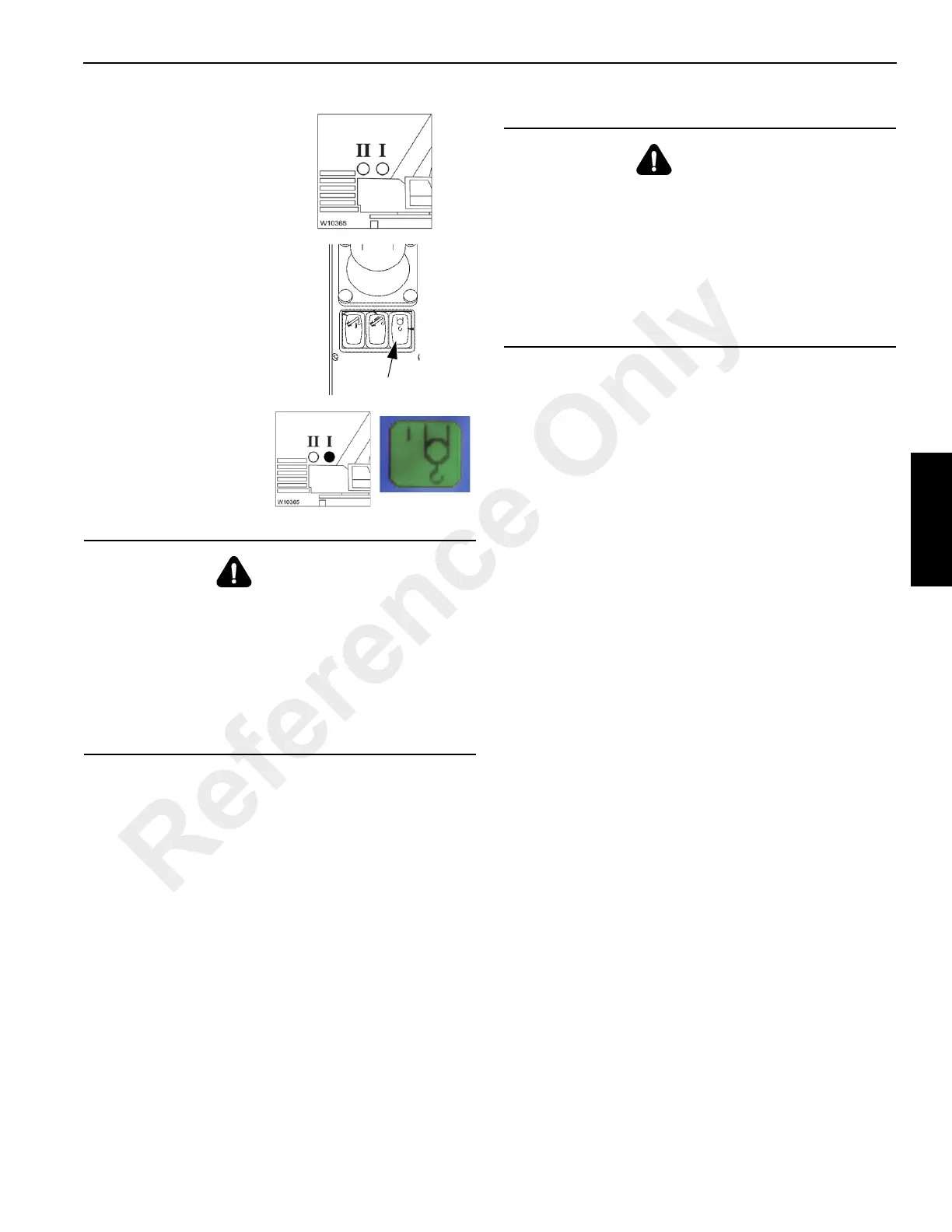
Verify Reeving
After selecting the hoist and making sure the associated
lamp is on verify that the reeving for that hoist is correct.
The indicator (3) (Figure 3-124) will show the last entered
reeving value for the main hoist.
If no reeving has been entered yet, the RCL selects 1 for the
reeving.
If necessary, enter the current reeving, refer to Entering the
Reeving, page 3-83.
Deploying the Outriggers
1. Engage the parking brake using switch on the steering
column, see Park Brake Switch, page 3-5.
2. Enable the four-wheel drive system using switch on the
steering column, see Drive Select Switch, page 3-5.
3. Position the outrigger floats directly out from each
outrigger to where the outriggers will be properly
extended.
4. Press the appropriate button on the outrigger menu and
hold to extend. The chosen outrigger beam(s) should
begin to extend. (Refer to Engaging the Mid-Extend
Lock Pin, page 3-125 if the crane is to be operated with
the outriggers at the mid-extend position.) Extend each
outrigger in turn. Refer to Outrigger Monitoring System
(OMS) RCL Display (Optional—Standard in North
America), page 3-125
NOTE: More than one outrigger at a time may be
extended. However, to ensure that each outrigger
is fully extended, repeat step 4 for each outrigger
after a multi-outrigger extension.
5. After all four outrigger beams have been fully extended,
press the appropriate button on the outrigger menu for
extending the desired jack and hold the button to extend.
Extend each jack, positioning the float as necessary,
until the locking levers of the float engage the jack
cylinder rod. Verify each float is secure on its related jack
cylinder rod.
NOTE: More than one jack may be extended at one time.
6. With each jack float firmly touching the ground, extend
the front jacks approximately 3 to 4 in (8 to 10 cm).
7. Extend the rear jacks approximately 3 to 4 in (8 to 10
cm).
8. Repeat steps 6 and 7 until all wheels are clear of the
ground and the crane is level as indicated by the bubble
level indicator on the right side control panel, see Level
Indicator, page 3-8.
3. The lamps I and II go
out.
4. Switch on the main hoist
by pressing the switch
once.
Now lamp I for the main
hoist is ON and the ECOS
indicator is green.
DANGER
Tipping Hazard!
After switching over the hoists, always check whether the
displayed reeving value corresponds to the current
reeving value of the displayed hoist and, if necessary,
enter the current reeving value.
This will prevent the RCL from making calculations based
on an incorrect reeving value and the crane from
becoming overloaded or from overturning.
DANGER
Tipping Hazard!
All four outrigger beams must be equally extended to the
mid-position vertical stripe with the lock pins engaged or
fully extended or retracted before beginning operation.
The operator must select the proper load chart and RCL
program for the outrigger position selected.
Serious injury or death may occur if the proper load chart
and RCL program are not used and the crane tips over.
Reference Only