OPERATING CONTROLS AND PROCEDURES RT9150E OPERATOR MANUAL
3-118
Published 2-23-2017, Control # 644-00
General Crane Operation
Pump Drive
The main hydraulic pumps are mounted on the torque
converter drive pad. The hydraulic oil cooler pump is
mounted on the engine. The pumps operate any time the
engine is running.
Operating the Crane On Outriggers
In order to operate the crane on outriggers:
• the transmission must be shifted into 4WD (four-wheel-
drive) for the outriggers to be deployed and
• the parking brake set.
When this procedure is correctly followed, the wheels will not
rotate with the crane on outriggers during any crane function.
Control Lever Operation
The control lever operation for all crane functions is
standard, i.e. the closer the lever is to neutral (center), the
slower the system responds. The control lever should be
returned to neutral to hold the load. Never feather the hoist
control lever to hold the load.
NOTE: Always operate the control levers with slow, even
pressure.
Preload Check
After the crane has been readied for service, an operational
check of all crane functions (with no load applied) should be
performed. The Preload Check is as follows:
NOTE: Carefully read and become familiar with all crane
operating instructions before attempting a preload
check or operating the crane under load.
1. Extend and set outriggers.
2. Raise, lower, and swing the boom a minimum of 45°
right and left.
3. Telescope the boom in and out.
4. Raise and lower the cable a few times at various boom
lengths. Ensure there is no kinking.
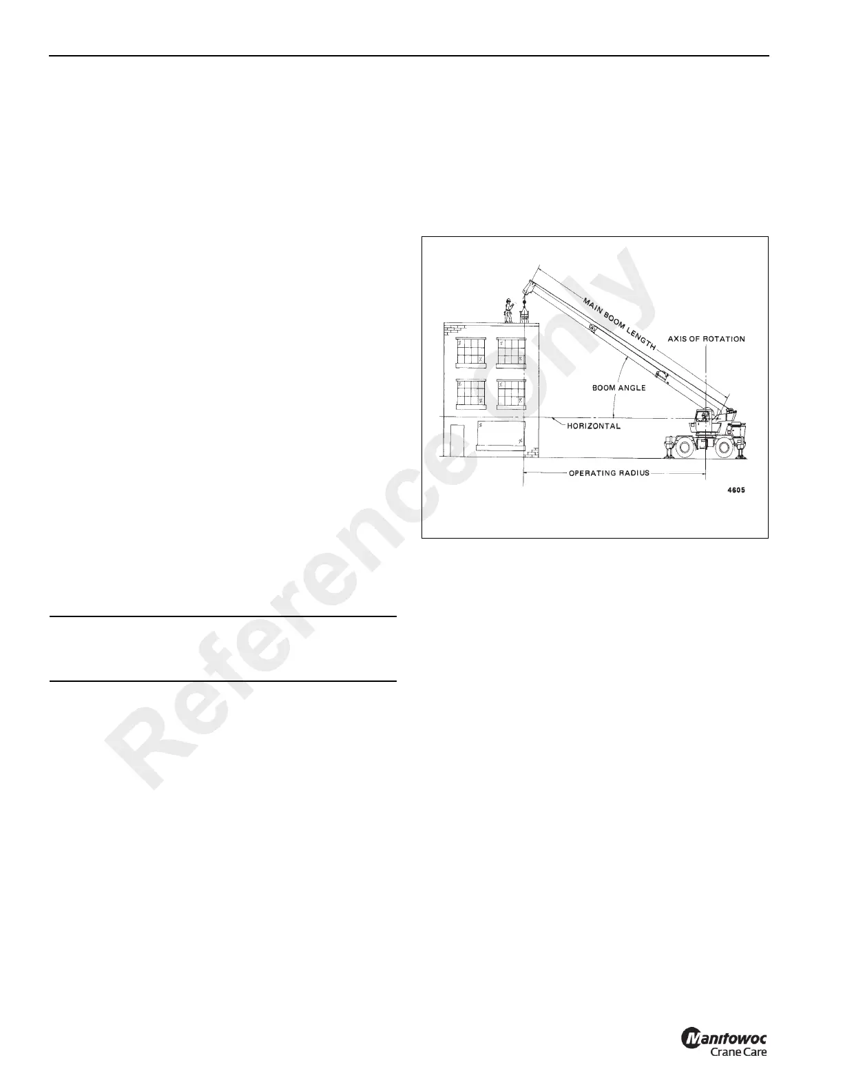
Using Your Load Chart
NOTE: One of the most important tools of every Grove
crane is the load chart found in the crane operator’s
cab. Terms to know are shown in (Figure 3-110).
The load chart contains a large amount of information, which
must be thoroughly understood by the operator.
The load chart contains outrigger capacity charts for fully
extended, mid extended, outriggers for the main boom and
boom extension, and fully retracted outrigger beams for main
boom only. In addition, the load chart contains two on-rubber
capacity charts: 360° stationary, and pick and carry over
front.
The capacity charts are divided into structural strength and
stability limits. This is shown by the bold line across the chart.
Capacities above the line are structural strength limits and
capacities below the line are stability limits.
The left column is the load radius, which is the distance from
the center of crane rotation to the load center of gravity. The
top row lists various boom lengths ranging from fully
retracted to fully extended or boom extension lengths and
offsets. The number at the intersection of the left column and
top row is the total load capacity for that load radius and
boom length or boom extension lengths offset. The number
in parentheses below the total load capacity is the required
boom angle (in degrees) for that load. Any boom length
between increments should always be treated as if it was the
next longer length. For example, if the actual boom length is
50 ft and the chart shows boom lengths of 48 and 54 ft, use
the load capacity shown in the 54 ft column.
Another important section is the range diagram. The range
diagram shows the operating radius and tip height that can
be achieved at a given boom length and angle. If the
operator knows the radius and tip height required for a
specific lift, the angle and boom length can be quickly
determined from the range diagram. Or, if the boom length
and angle are known, the tip height and operating radius can
be quickly determined.
CAUTION
Operate engine at or near governed rpm during preload
check of crane functions.
Reference Only