3-15
RT9150E OPERATOR MANUAL OPERATING CONTROLS AND PROCEDURES
Published 2-23-2017, Control # 644-00
Hoist Rotation Indicators
The Hoist Rotation Indicators (4) are located on each hoist
control lever. The indicators are electronically driven by a
signal from an electronic transmitter and sensor attached to
each hoist. A pulsating signal is sensed by the operator’s
thumb during hoist operation.
Swing Gear Switch
The Swing Gear Switch (5) is located on the left armrest. The
switch is used to activate the swing gear control circuit in
order to rotate the superstructure. Push the top of the switch,
the icon on the ECOS display will turn green. Use the
swing gear controller (1) to rotate the superstructure after the
switch is turned on. Push the top of the switch again to turn
the function off.
Crane Function Switch
The Crane Function Switch (6) is located on the left armrest.
The switch is used to stop all crane functions to prevent
inadvertent operation of functions due to bumping the
controllers while roading or other operation. Push the top of
the switch: the icons on the ECOS display will turn red;
swing, both hoists, lift, telescope and the luffing jib will
become inoperative.
To activate a craning function after pressing this switch,
press the appropriate function’s switch.
Auxiliary Hoist (II) Switch
The Auxiliary Hoist Switch (7) is located on the left armrest.
The switch is used to turn on the auxiliary hoist function by
pushing the top of the switch. Use the joystick controller (1)
to activate the auxiliary hoist function after switch is turned
on. Push the top of the switch again to turn the function off.
Differential Lock Switch (Optional)
The Differential Lock Switch (8) is located on the left armrest
and is used to lock the right and left wheels in a tandem set.
The differential lock increases traction on slippery roads. The
differential lock switch is a momentary rocker switch.
NOTE: Release the throttle before using this switch.
Push and hold the top of the switch to engage the differential
lock, the icon on the ECOS display will turn red.
Release the switch to dis-engage the differential lock.
Rear Steer Control Switch
The Rear Steer Control Switch (9) is located on the left
armrest. Push the top of the switch to turn the rear wheels to
the right, causing the crane to turn to the left. Push the
bottom of the switch to turn the rear wheels to the left,
causing the crane to turn to the right. Release the switch to
return to the center off position. An indicator on the ECOS
main menu indicates if the rear wheels are not centered.
Lift Switch (CE Option)
The Lift Switch (10) is located on the left armrest. When in an
overload condition the RCL will lockout boom lift. Push the
top of the switch to override the lockout condition to
decrease the boom radius by raising the boom.
MISCELLANEOUS CAB CONTROLS AND
FEATURES
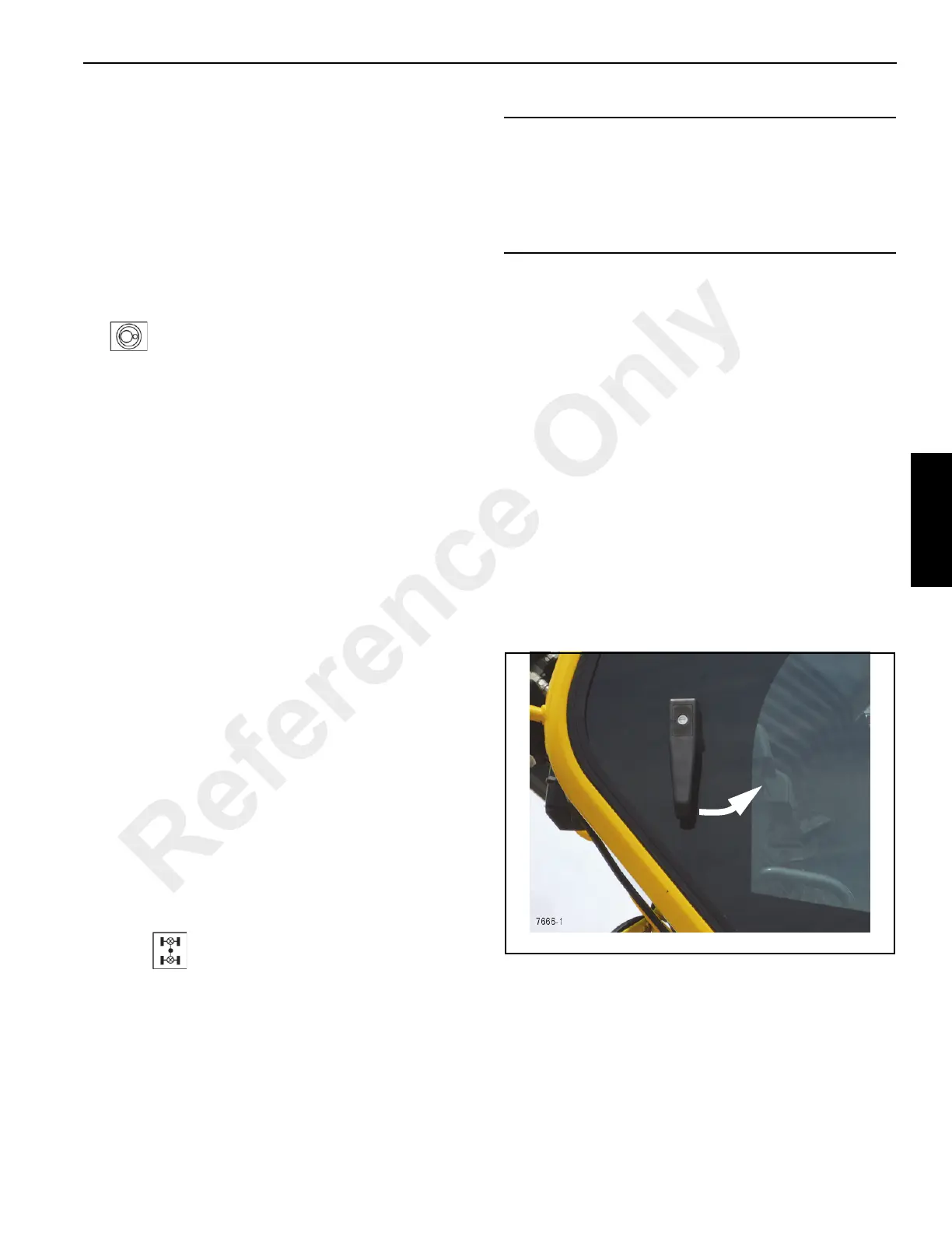
Cab Door
Outside Handle/Latch
Refer to Figure 3-11.
Rotate the handle counterclockwise to release the door latch
and slide the door to the rear.
After exiting the cab pull the handle towards the front of the
cab, sliding the door completely until it latches.
CAUTION
Vehicle Control Hazard!
Do not operate the differential lock on dry roads, while
the crane wheels are spinning or at speeds over
approximately 10 mph (16 km/h). Damage to the
vehicle may result.
Reference Only