SET-UP AND INSTALLATION RT9150E OPERATOR MANUAL
4-54
Published 2-23-2017, Control # 644-00
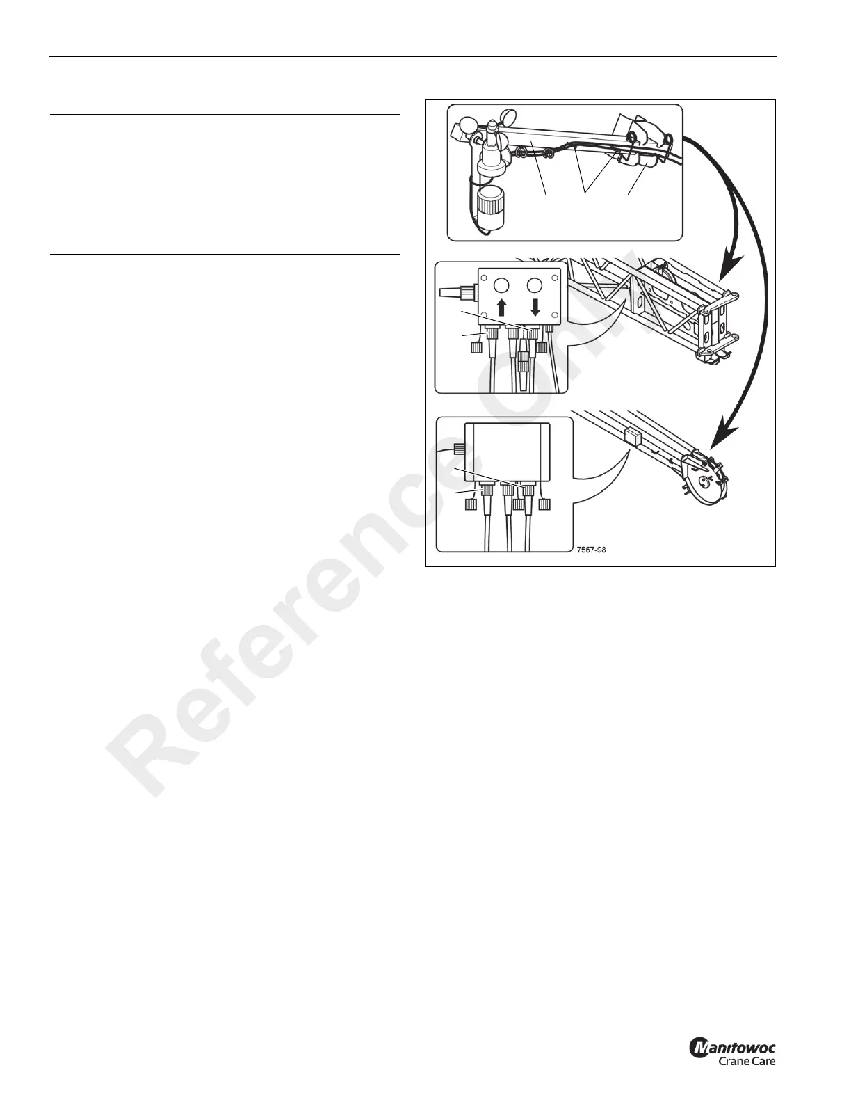
ANEMOMETER/AIRCRAFT WARNING LIGHT
Mounting Anemometer/Aircraft Warning
Light
1. Insert the mounting arm (1) (Figure 4-90) into the holder
(3) and secure it with the retaining clips.
2. Remove the cable from the clamps (2); connect the
anemometer cable to the socket (4), connect the aircraft
warning light cable to the socket (5).
3. Arrange the cable so that it will not be damaged during
crane operation.
4. Check that the anemometer is able to swing free so that
it hangs vertically at different boom angles.
Removing Anemometer/Aircraft Warning
Light
1. Take the plugs out of the sockets (4 and 5) (Figure 4-90)
and install the protective caps.
2. Wind the cable onto the clamps (2).
3. Remove the mounting arm (1) from the holder (3).
4. For transportation, fasten the retaining clips to the
mounting arm (1).
CAUTION
Equipment Damage Hazard!
Always remove the anemometer/aircraft warning light
before transporting the crane.
This prevents damage by overhead obstructions and the
anemometer from being damaged due to excessive air
speeds.
1
FIGURE 4-90
2
3
36 ft (11 m) Extension
59 ft (18 m) Extension
4
5
4
5
Reference Only