SET-UP AND INSTALLATION RT9150E OPERATOR MANUAL
4-26
Published 2-23-2017, Control # 644-00
12. For units equipped with a hydraulic luffing extension,
establish hydraulic connections between the extension
and the main boom, refer to Establishing the Hydraulic
Connection, page 4-35.
NOTE: You can also install the folding boom extension in
front of the inserts when changing from a 59 ft
extension to a longer boom extension.
Securing Extension with Tag Line (Rope)
The extension may swing out on its own when the last
connection is removed that held the extension at the side of
the main boom.
The extension must be secure before beginning the erection
procedure.
Secure the extension as follows:
• Attach a tag line at the front of the extension.
• Guide the tag line underneath the extension and
through a bracket on the main boom and back
again.
• Have a helper hold the tag line tight while removing
the last connection.
NOTE: If alone, secure the other end of the tag line on the
crane (e.g. on the steps of the access ladder to the
carrier or to the hole in the superstructure). Leave
enough play in the tag line that it is tight only when
you swing the lattice extension towards the main
boom head later on.
Relieving the Load on Connecting Lugs
NOTE: The weight of the extension can cause the
connecting lugs on the left side to be misaligned or
the pins to become wedged which makes it difficult
to install or remove the pins.
When installing or removing the pins and the connecting lugs
do not align:
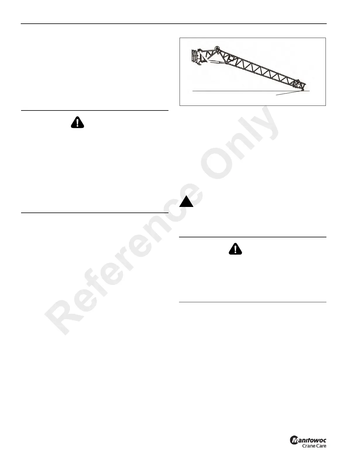
1. Lower the boom until the nose of the extension is on the
ground or suitable support (1) (Figure 4-29). If
necessary, override the lifting limit switch.
2. Continue to lower carefully until the connecting points
align or until the load has been removed from the pins.
Extension Erecting Warnings and
Requirements
Before you erect a boom extension, the following
requirements must be met:
• The folding extension is mounted on the side of the main
boom and is in the transport condition.
• The crane is level, supported on outriggers according to
the Load Chart for the planned operation with the
configured extension.
• The main boom is completely retracted and has been
lowered into a horizontal position.
Erecting Procedure: 36 ft (11 m) Extension
This procedure is for erecting just the 36 ft extension, leaving
the 23 ft extension attached to the main boom.
DANGER
Crushing Hazard!
Always secure the boom extension with a tag line (rope)
on the main boom before removing any connections. This
will prevent the extension from slipping off the run-up
ramp, swinging around and knocking you off the carrier or
injuring other persons in the swing range.
Before actuating swing or any other function, sound horn
and verify that all personnel are clear of rotating and
moving parts.
Death or serious injury could result from being crushed by
moving machinery.
Before attempting to erect or stow the boom
extension, read and strictly adhere to all danger
decals installed on the extensions and stowage
brackets.
DANGER
Crushing Hazard!
Main boom angles are used to control speed at which
extensions swing during erecting and stowing procedure.
Improper boom angles will cause uncontrollable swing
speeds of the extension, which may cause death or
serious injury.
Reference Only