4-37
RT9150E OPERATOR MANUAL SET-UP AND INSTALLATION
Published 2-23-2017, Control # 644-00
Deploying the Front Deflection Sheave
1. Remove the retaining clip from the pin (2) (Figure 4-55).
2. Hold the deflection sheave by the strut (1) and pull out
the pin (2).
3. Fold the deflection sheave (3) up and fasten it in this
position with the pin.
4. Secure the pin (2) using the retaining clip.
Folding In Front Deflection Sheave
1. Remove the retaining clip from the pin (2) (Figure 4-55).
2. Hold the deflection sheave by the strut (1) and pull out
the pin (2).
3. Fold the deflection sheave (3) down and fasten it in
position with the pin (2).
4. Secure the pin (2) using the retaining clip.
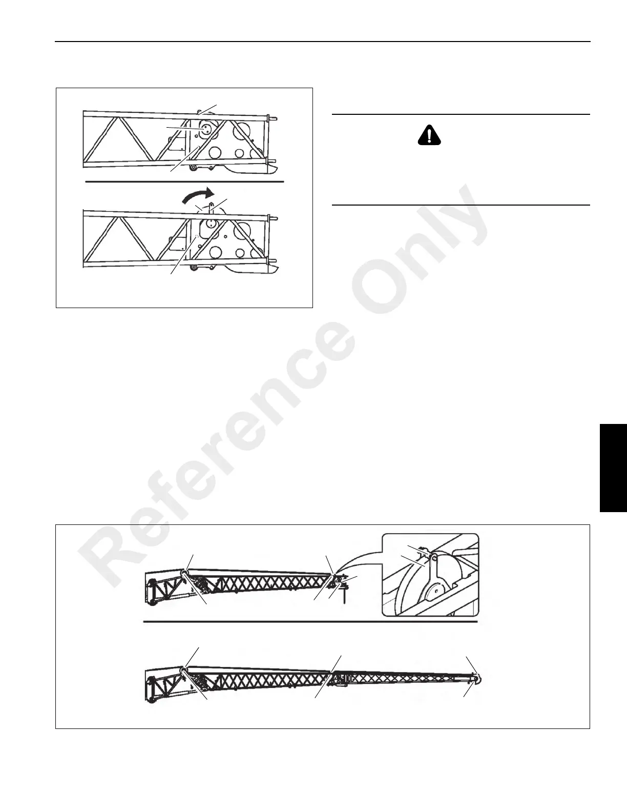
Positioning/Removing the Hoist Cable
Positioning Hoist Cable
1. Remove the retaining sheaves (1) (Figure 4-56).
2. Guide the wire rope over the deflection sheaves (4), (3)
and over the nose sheave (2) of the extension.
3. Reinstall all the retaining sheaves (1) and secure with
retaining clips.
4. Install the hook tackle or the hookblock. The wire rope
may now be reeved once or twice, depending on the
length of the section.
Removing Hoist Cable
1. Unreeve the hookblock.
2. Remove the retaining sheaves (1) (Figure 4-56).
3. Take the wire rope off the head sheave (2) and
deflection sheaves (4), (3) and place it on the ground on
the left side.
4. Replace all retaining sheaves and secure them with
retaining clips.
CAUTION
Falling Objects Hazard!
Always make sure sheaves and pins that secure the hoist
cable are secured with clips. This prevents components
from coming loose, falling and causing injury.
FIGURE 4-56
11 m (36 ft) Swingaway Lattice
18 m (59 ft) Swingaway Lattice
1
1
1
1
1
1
2
3
2
1
3
4
4
3
Reference Only