10 ISDN-U I/O CARD
3021M100-002
10-3
The edge connector fixes the card to any one of the motherboard’s expansion slots
1-8.
The connector plate fixes the female RJ-45 connector to the chassis’ rear panel
with two Phillips-head screws and limits dust accumulation and electromagnetic
radiation.
10.1.1 ISDN Port Signal Handling
When the ISDN-U I/O Card is connected to the network, signal LEDs indicate th
status of the connection. The SYNC LED indicates that the D channel is signaling
the switch at the Local Exchange (LE). The 2 LEDs labeled B1, for B channel 1,
and B2, for B channel 2, indicate data transmission on that channel.
10.1.2 Power
Power
Consumption
2.5 Watts (8.5 BTU/hr).
Power Source
The motherboard 120-pin connector supplies +5 VDC to the card and provides the
Ground return.
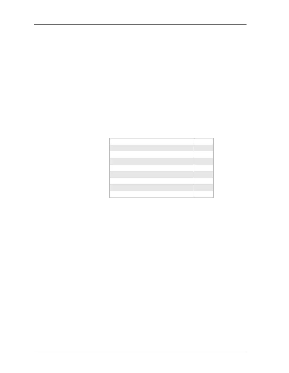
Table 10-1 Signal Pin-Outs for ISDN-U Port
Signal Pin No.
not connected 1
not connected 2
not connected 3
Tip 4
Ring 5
not connected 6
not connected 7
not connected 8