CX950 Hardware Reference Manual
18-4
3021M100-002
the T1/E1 lines; see Figure 18-3.
Status-
Indicator LEDs
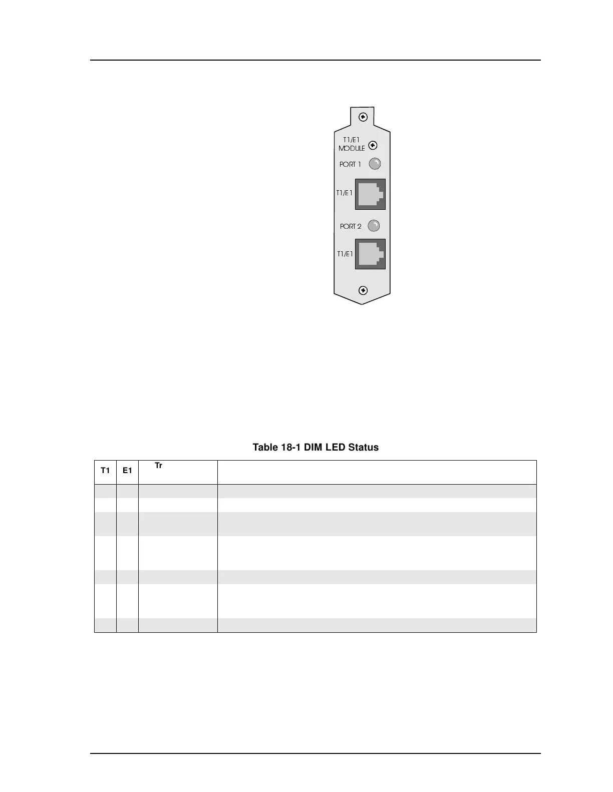
Two tri-coloured LEDs are mounted on the connector plate for indicating the
status of each T1 or E1 line. The LEDs are under software control and can display
three different states: OFF, ON, and flashing. Table 18-1 lists the indications
associated with the various LED states and their applicability to either T1 or E1
ports.
Figure 18-3 Digital Interface Module Connector Plate
Table 18-1 DIM LED Status
T1 E1
Tri-coloured
LED State
Indication
√ √
Off T1 or E1 physical line is completely disabled.
√√
Green T1 or E1 physical line is fully operational.
√
Yellow
Yellow Alarm at the T1 physical line. This condition will persist until it is cleared, at which
time the LED will change colour to reflect the change in status.
√√
Red
Loss of Frame (LOF) or a Loss of Signal (LOS) at the T1 or E1 physical line. These con-
ditions, commonly known as Red Alarm cannot be distinguished, and will persist until the
condition is cleared. The LED will then change colour to reflect the change in status.
Flashing Green Not used.
√
Flashing Yellow
Alarm Indication Signal (AIS) at the T1 physical line. This condition, commonly known as
Blue Alarm will persist until it is cleared, at which time the LED will change colour to
reflect the change in status.
Flashing Red Not used.