6 UNIVERSAL I/O CARD
3021M100-002
6-3
6.1.3 Programmable Headers
Programmable headers enable the hardware configuration of the serial I/O ports.
The Universal I/O card contains three sets of five miniature surface-mount sockets
that are populated with small PCBs. The orientation of the PCBs determines the
configuration of the physical protocol (V.24, V.35, or X.21), interface (DTE or
DCE), and clock source (internal or external) for each port.
6.1.4 Universal I/O Connector Plate
Port
Connector
The Universal I/O connector plate features one 68-pin Very High Density Cable
Interconnect (VHDCI) connector for external connections to the network; se
Figure 6-3. All five I/O ports share this single connector.
Status-
indicator LED
Three LEDs are visible through the connector plate which indicate the status o
the link. Any of the five links can be monitored by setting the thumbwheel to the
appropriate port. The LEDs are under software control and can display two states:
ON and OFF. Table 6-1 lists the indications associated with the LED states and
their applicability to either DTE or DCE operation.
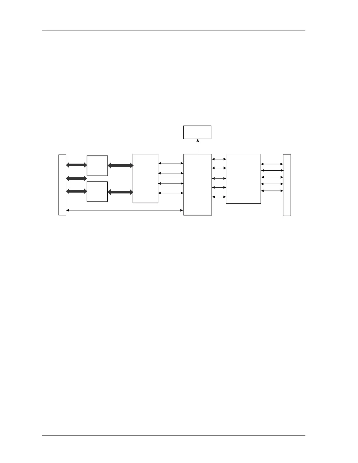
Figure 6-2 Universal I/O Card, Simplified Block Diagram
CX950
I/O BUS
QUICC LINE
INTERFACE
DRIVERS
ADDRESS
BUS
DATA
BUS
CONTROL
ADDRESS
LATCHES
DATA
XCEIVERS
PORT 2
PORT 2
PORT 5
PORT 5
PORT 1
PORT 1
PORT 4
PORT 4
PORT 3
PORT 3
PROGRAMMABLE
HEADERS
STATUS
INDICATING
LEDS
I/O
CONNECTOR
PLATE