19 ATM I/O CARD
3021M100-002
19-3
19.1.5 PHY Device
The PHY device is responsible for decoupling its upper interface from its lower
interface. At its upper interface, the PHY device supports the standardized Utopia
interface to the SAR. At its lower interface, the PHY device provides an interfac
to the physical line via an external T1/E1 Framer. Both interfaces are decoupled
via the PHY’s insertion of idle cells, which ensures the line rate of the lower
interface is filled when no data is received from the upper interface (Utopia bus).
19.1.6 T1/E1 Framer
The T1/E1 Framer is used to accept and generate coding such as Binary 8-Zero
Substitution (B8ZS), High Density Bipolar order 3 (HDB3), and Alternate-Mark-
Inversion (AMI) on the T1/E1 line interface. The interface to the PHY devic
generates and receives CMOS logic levels for the clock and data.
19.1.7 CX950 I/O Bus
The exchange of configuration and status information of the PHY device and T1/
E1 Framer is handled by the CX950 system I/O bus. Connection of the I/O bus to
the motherboard is via a 120-pin card edge connector.
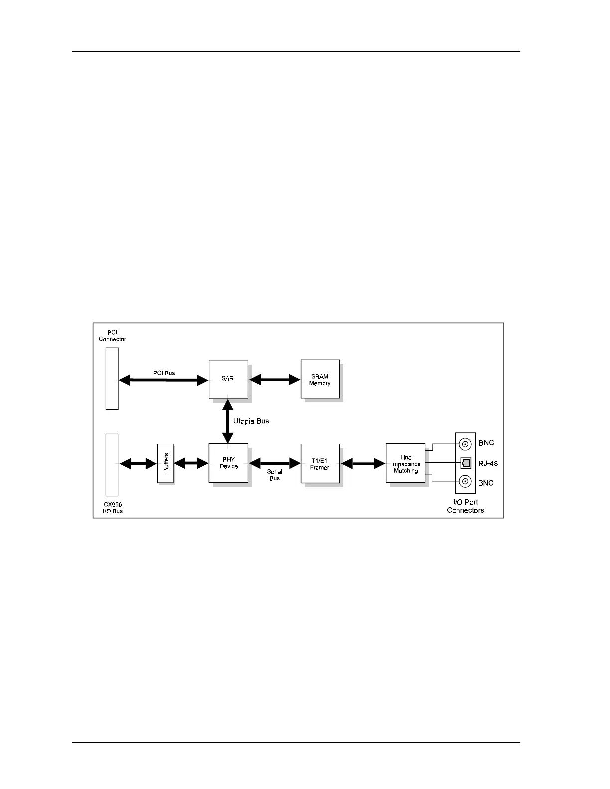
Figure 19-2 ATM I/O Card, Simplified Block Diagram