13 V.34 MODEM I/O CARD
3021M100-002
13-3
The edge connector fixes the card to any one of the motherboard’s expansion slots
1-8.
The connector plate fixes the female RJ-11 connector and audio jack to the
chassis’ rear panel with two Phillips-head screws and limits dust accumulation
and electromagnetic radiation.
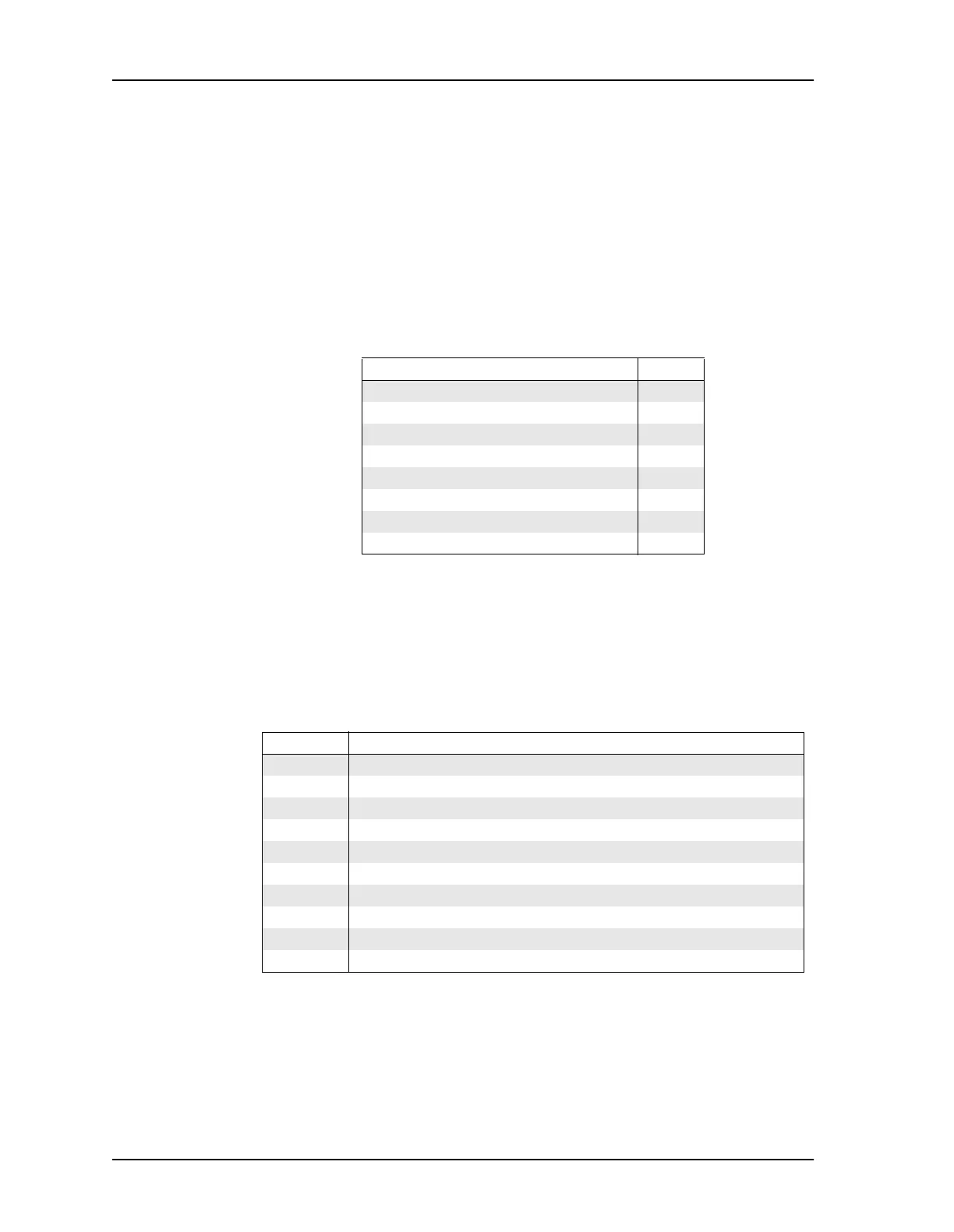
13.1.1 V.34 Modem Signal Handling
The following table describes the signal to pin relationships for the V.34 modem.
13.2 Modem Capabilitie
The V.34 Modem I/O card acts as an originate or answer modem using any of the
protocols listed in the table below.
Table 13-1 V.34 Modem Pin-Outs
Signal Pin No.
not connected 1
not connected 2
Ring 3
Tip 4
not connected 5
not connected 6
not connected 7
not connected 8
Table 13-2 V.34 Modem Protocol/Rate Support
Protocol Possible Data Rates (bps)
Bell 103 300
V.21 300
Bell 212 1200
V.22 1200
V.22bis 2400 or 1200
V.23 1200
V.32 9600 or 4800
V.32bis 14400, 12000, 9600, 7200 or 4800
V.FC 28800, 26400, 24000, 21600, 19200, 16800 or 14400
V.34 28800, 26400, 21600, 19200, 16800, 14400, 12000, 9600, 7200, 4800 or 2400