CX950 Hardware Reference Manual
17-4
3021M100-002
The following table describes jumper settings for the correct line impedance fo
E1 through either the RJ-48 or the BNCs.
* Installing these jumpers at LK7 and LK8 will connect the BNC Ring terminal to
Frame Ground.
Table 17-2 T1 Line Impedance
Jumper Port T1 RJ-48 (100 Ohms) Configuration
LK2 T1 Transmit Connect pin 1 to 2
LK3 T1 Transmit Connect pin 1 to 2
LK5 T1 Receive Connect pin A1 to B1
LK6 T1 Receive Connect pin A1 to B1
LK7 T1 Transmit Remove Jumper
LK8 T1 Receive Remove Jumper
Table 17-3 E1 Line Impedance
Jumper Port RJ-48 (120 Ohms) Configuration BNC (75 Ohms) Configuration
LK2 E1 Transmit Connect pin 2 to 3 Connect pin 2 to 3
LK3 E1 Transmit Connect pin 2 to 3 Connect pin 2 to 3
LK5 E1 Receive Connect pin A2 to B2 Connect pin A3 to B3
LK6 E1 Receive Connect pin A2 to B2 Connect pin A3 to B3
LK7 E1 Transmit Install Jumper Install Jumper*
LK8 E1 Receive Install Jumper Install Jumper*
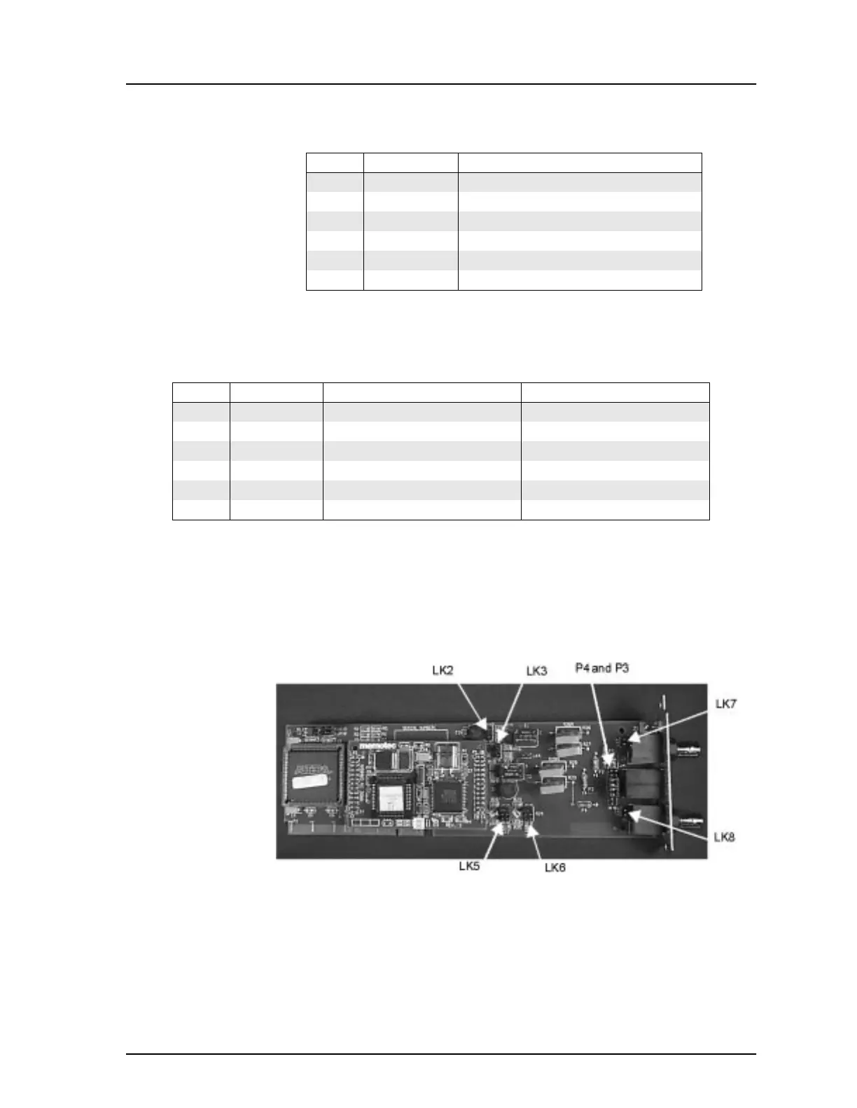
Figure 17-3 T1/E1 Configuration Jumpers