CX950 Hardware Reference Manual
6-6
3021M100-002
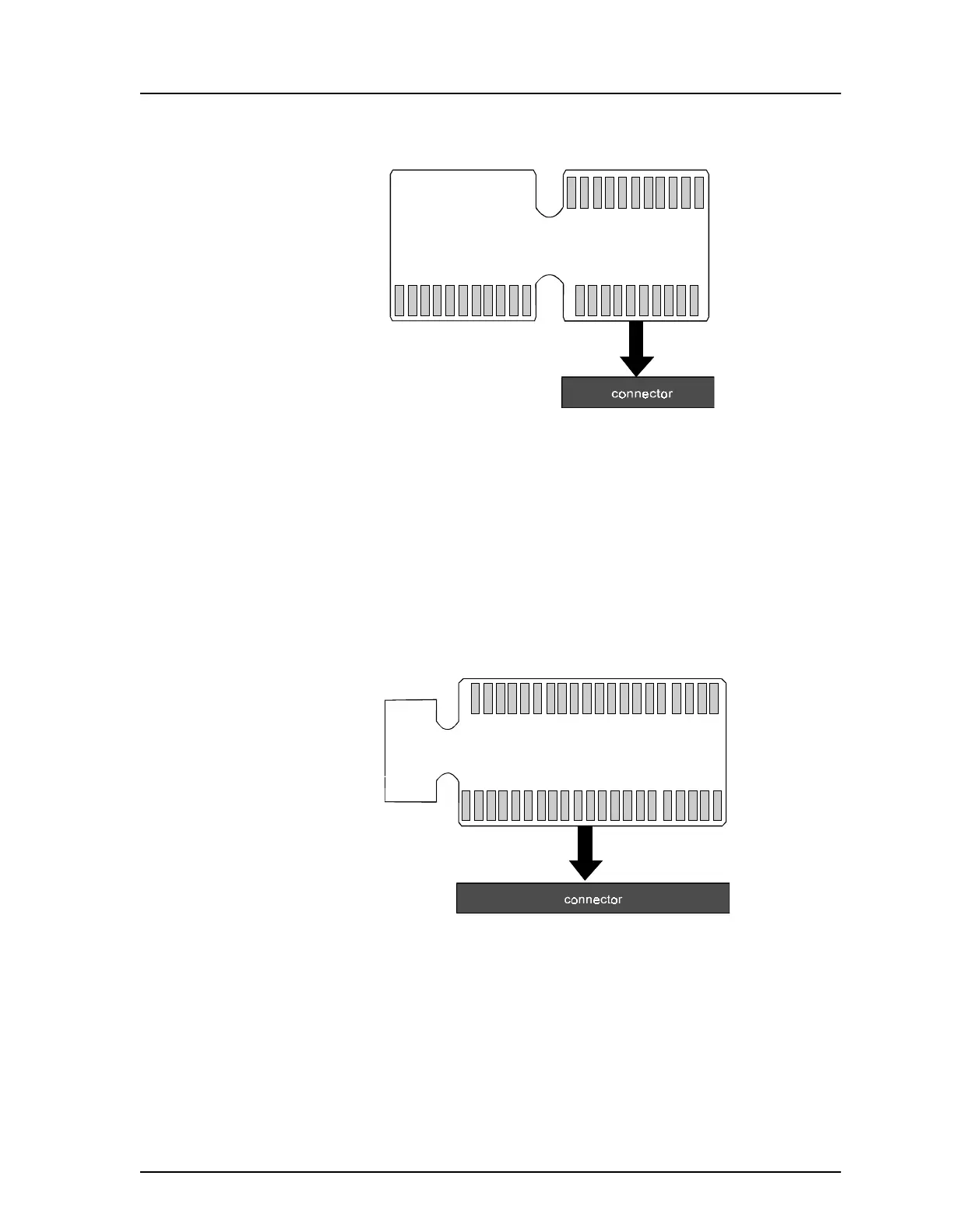
6.3.2 DTE/DCE Configuration
DTE/DCE selection for each port is configured by inserting the appropriate edge
of the PCB into the connector. DTE/DCE port configuration connectors are
located at J11, J21, J31, J41 and J51. Figure 6-5 demonstrates the PCB orientation
for DTE configuration.
Figure 6-4 Configuring the V.35 Protocol
1
V.35
11
21 12
X.21
V.24
Figure 6-5 Configuring DTE Operation
121
DTE
DCE