21 INSTALLATION AND CONFIGURATION
3021M100-002
21-7
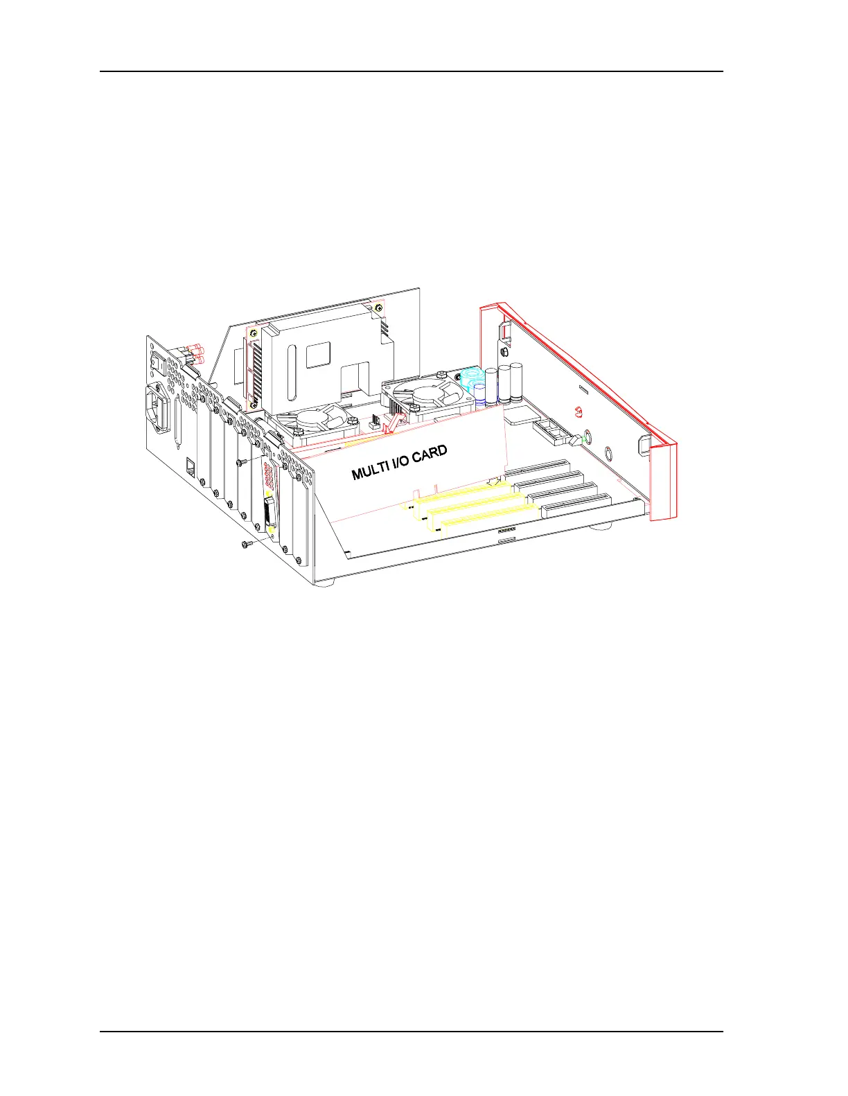
7. Insert the card through the slot’s opening in the rear panel, then align the
card’s edge connector over the slot’s associated connector on the
motherboard.
Connector J19 is associated with slot 1, J18 with slot 2, J17 with slot 3, J16
with slot 4, J15 with slot 5, J14 with slot 6, J13 with slot 7 and J12 with slot 8.
8. Press the card firmly, but gently, into place.
9. Fasten the card’s connector plate to the rear panel.
10. Repeat steps 1-8 for each I/O card you want to install.
11. Replace the cover (see Procedure 2) or proceed with other work in the chassis.
Figure 21-2 Standard I/O Card Installation