CX950 Hardware Reference Manual
7-6
3021M100-002
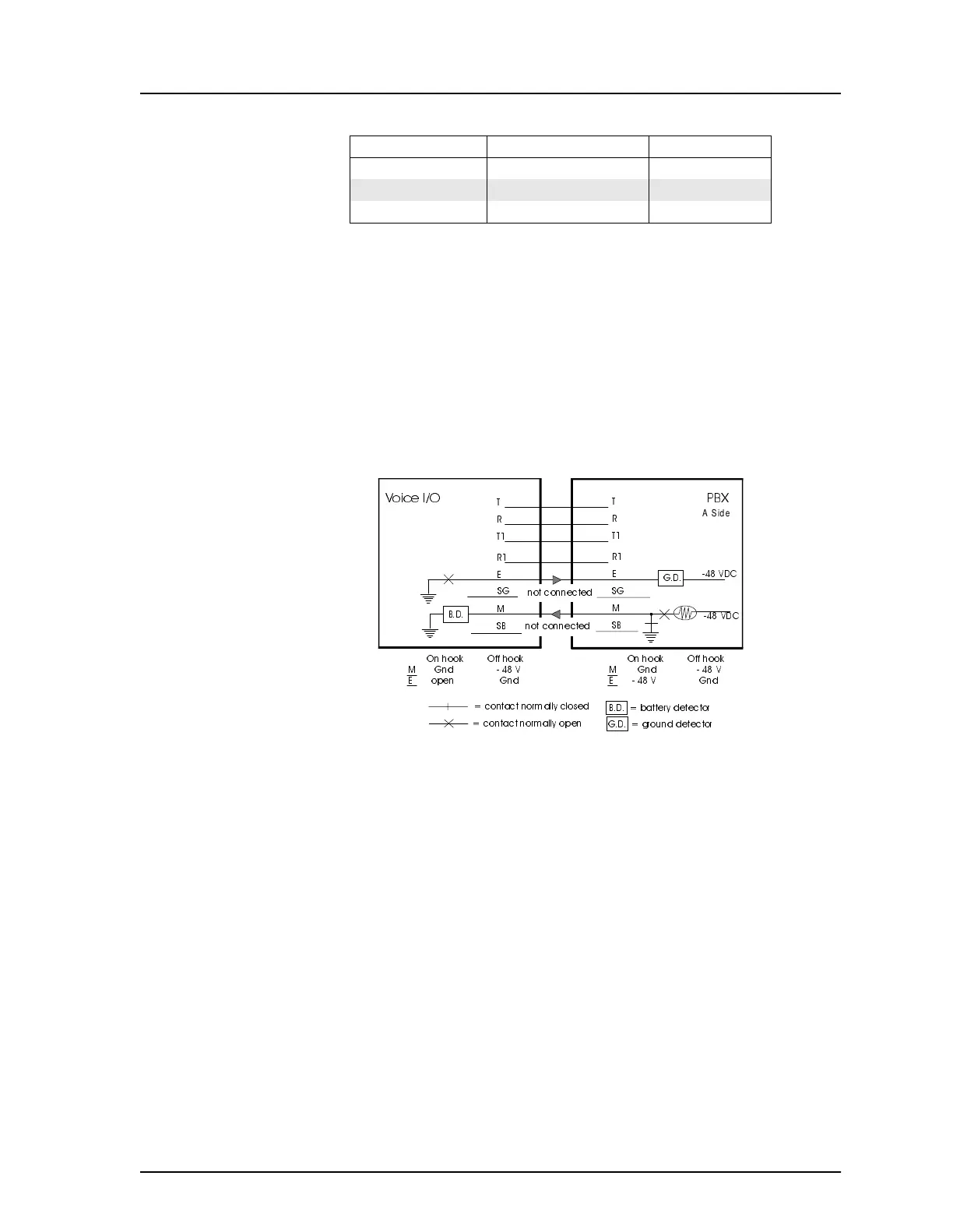
7.5 Layouts for E&M Signaling Leads
The following diagrams illustrate the arrangements for normal signaling of E&M
4-wire Types I, II, III, IV and V. The same diagrams apply to the E&M 2-wir
driver except that T1 to T1 and R1 to R1 connections are not present. The E&M
connects to a PBX which would determine the type.
6R1 RxB
7SG SG
8SB SB
Table 7-4 Voice Connector Signal Output (PB-45)
8-pin North American European
Figure 7-3 E&M Signal, 4-Wire Type I
!
"
#$
ASide