17 T1/E1 I/O CARD
3021M100-002
17-3
17.1.1 Port Configuration Jumpers
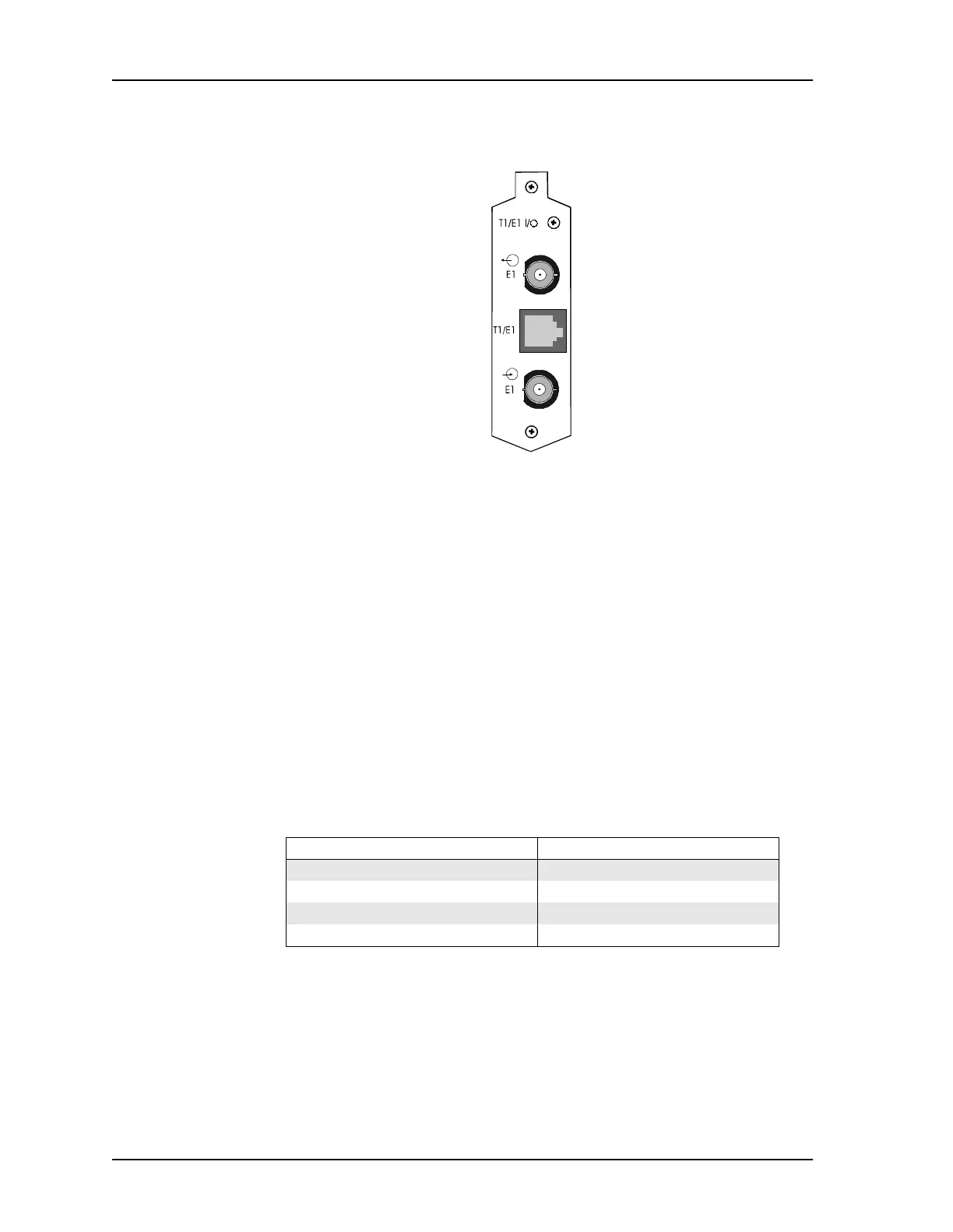
The T1/E1 I/O Card has connectors to mount either a T1 or E1 Line Interfac
Driver (LID). The I/O also has a number of 2-pin connectors that can be modified
with suitcase jumpers to select the port and match line impedance. For T1, the I/O
must be configured for connection through the RJ-48 connector. For E1, the I/O
can use either the RJ-48 or the two BNCs, depending on the network. When the
correct port has been selected the line impedance can be set.
Table 17-1 describes the jumper configurations required to select either the RJ-48
or the BNC connectors. Table 17-2 and Table 17-3 describe the jumper
configuration required to match the correct line impedance.
.
The following table describes the jumper settings for the correct line impedance
for T1 through the RJ-48 connector.
Figure 17-2 T1/E1 I/O Card, Connector Plate
Table 17-1 T1/E1 Connector Selection
For RJ-48 Connector For BNC Connectors
Connect pin 3 of P3 to pin 3 of P4 Connect pin 1 of P3 to pin 1 of P4
Connect pin 4 of P3 to pin 4 of P4 Connect pin 2 of P3 to pin 2 of P4
Connect pin 5 of P3 to pin 5 of P4 Connect pin 7 of P3 to pin 7 of P4
Connect pin 6 of P3 to pin 6 of P4 Connect pin 8 of P3 to pin 8 of P4