11 ISDN-S/T I/O CARD
3021M100-002
11-3
The edge connector fixes the card to any one of the motherboard’s expansion slots
1-8.
The connector plate fixes the female RJ-45 connector and signal LEDs to the
chassis rear panel with two Phillips-head screws and limits dust accumulation and
electromagnetic radiation.
The configuration jumpers allow the ISDN-S/T I/O card to be configured as
Terminal Equipment (TE) or as Network Termination (NT).
11.1.1 ISDN-S/T Jumper Settings
The ISDN-S/T I/O card has a number of pin connectors that can be modified with
suitcase jumpers to change the configuration of the ISDN-S/T I/O card. Thes
include jumpers for configuration and termination. The location of thes
connectors, labeled LK 1 through LK 9, are shown in Figure 11-1.
Configuration
For Network Termination (NT) configuration, connect pins 1 and 2 of th
appropriate connector. For Terminal Equipment (TE) configuration, connect pins
2 and 3 of the same connector. The following table provides the list of connectors
and their jumper settings.
Termination
For a CX950 with an I/O configured as NT or if it is the last TE on the line,
termination must be turned ON by connecting pins 1 and 2 at LK 7 and LK 9. The
ISDN-S/T I/O card comes from the factory with the termination set to ON.
If the ISDN-S/T I/O is configured as TE and it is not the last TE on the line,
termination must be turned OFF by connecting pins 2 and 3 at LK 7 and LK 9.
11.1.2 ISDN-S/T Port Signal Handling
The signal-to-pin relationships on the RJ-45 connector are different for an ISDN
S/T I/O card configured as TE (user side) or NT (network side). Table 11-2 shows
the signal pin-outs for each configuration.
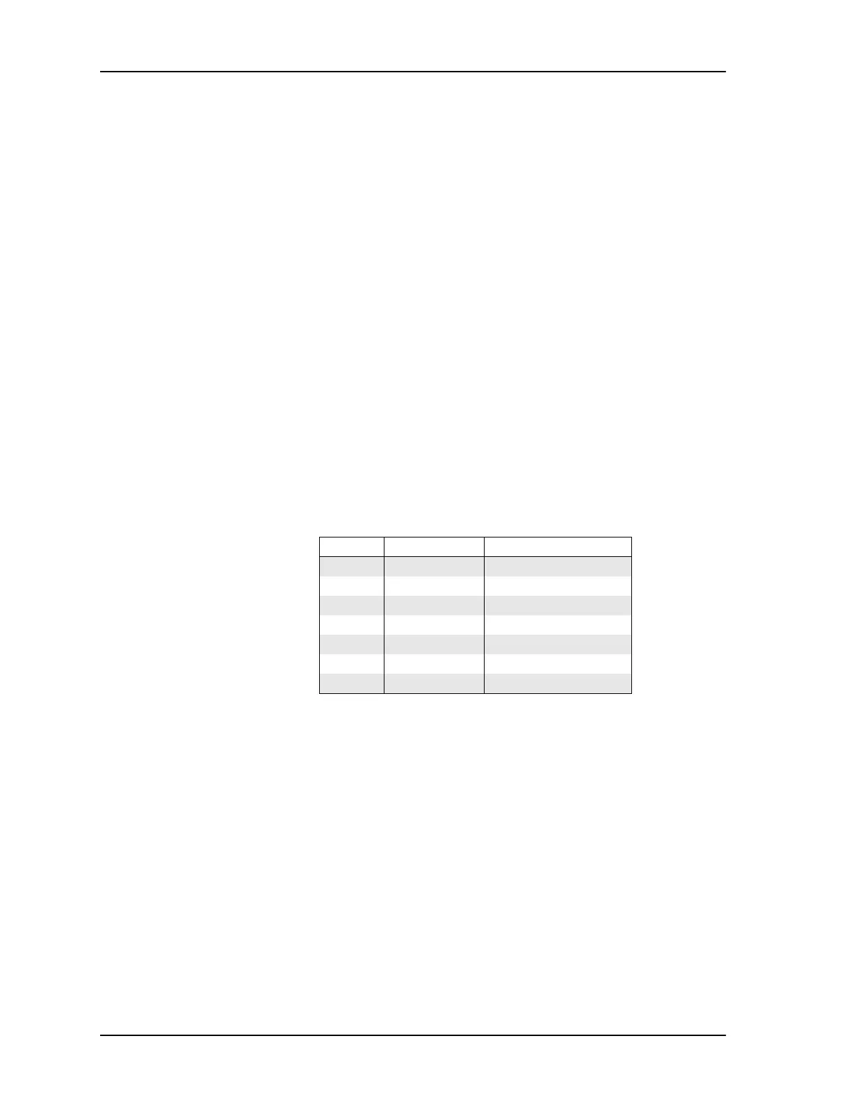
Table 11-1 ISDN-S/T Connector Jumper Settings
Connector NT Configuration TE Configuration (Default)
LK1 pins 1-2 pins 2-3
LK2 pins 1-2 pins 2-3
LK3 pins 1-2 pins 2-3
LK4 pins 1-2 pins 2-3
LK5 pins 1-2 pins 2-3
LK6 pins 1-2 pins 2-3
LK8 pins 1-2 pins 2-3