5 MULTI I/O CARD
3021M100-002
5-3
5.1.1 DTE/DCE Interface Configuration
Each of the five V.24/EIA-232 ports can be configured either as a DTE or DCE
device.
NOTE:
Other V.24/EIA-232 ports in the CX950 are DTE/DCE configured with a
jumper bank. Each port on the Multi I/O are DTE/DCE configured with a
jumper bank and a suitcase jumper.
DCE
When configured as a DCE device, the port transmits DCD, DSR and CTS and the
synchronous clock signals TXC and RXC. The port must receive DTR and RTS
from the attached DTE. Terminals, printers, controllers and hosts are always DTE
devices.
DTE
When configured as a DTE device, the port transmits DTR, RTS and EXTC and
receives DCD, DSR and CTS and the synchronous clock signals TXC and RXC
from the attached DCE.
Each port has a jumper bank (located at U29 through U33) and a set of pins for
suitcase jumpers (located at LK1 through LK5) to provide DTE/DCE
configuration. The orientation of each jumper bank determines whether the port
will be DTE or DCE. Rotating each jumper 180 degrees changes the port from
one kind of device to the other. The configuration guide for both DTE and DCE is
printed on the Multi I/O.
In addition, suitcase jumpers, at LK1 through LK5, must also be installed. Fo
each port configured as DTE, connect pin 1 to pin 2, for each port configured as a
DCE, connect pin 2 to pin 3.
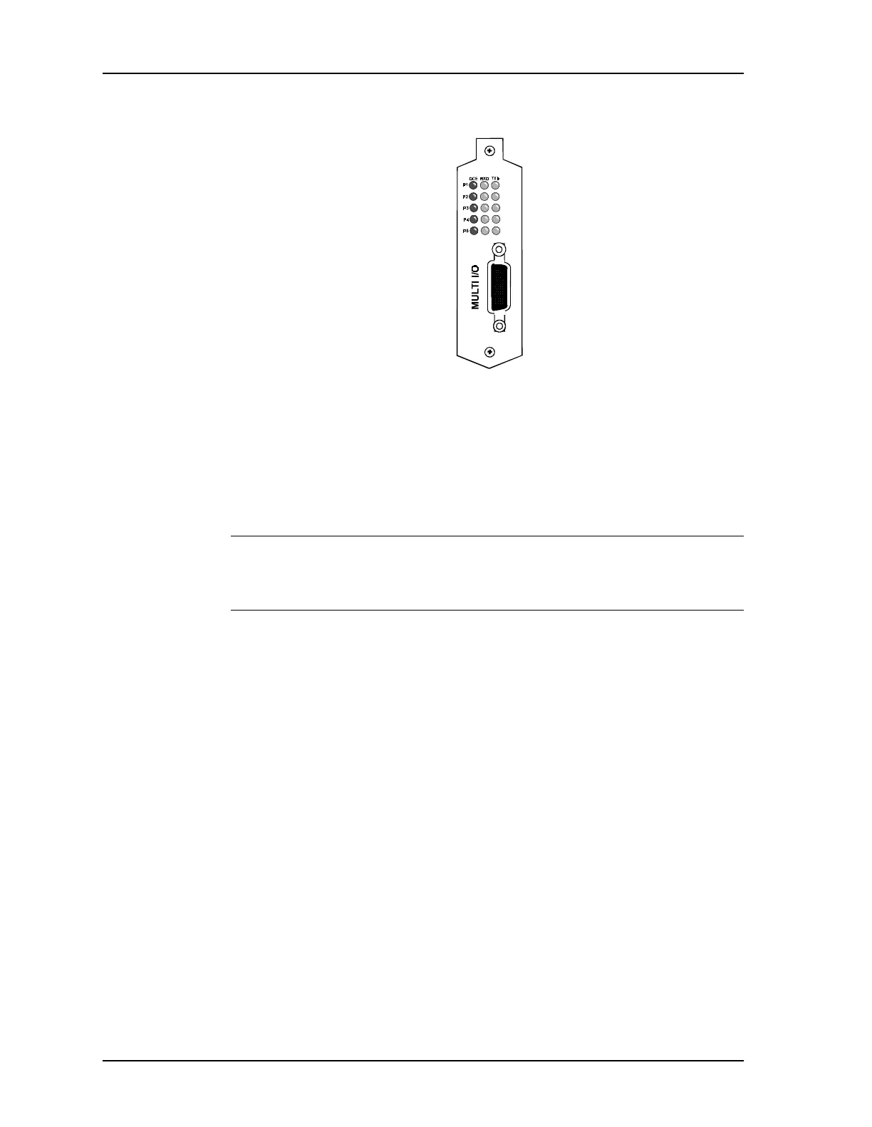
Figure 5-2 Multi I/O Card, Connector Plate