Page 30
Operation
optoNCDT 1402
Triggering6.6
The ILD1402 measurement output is controllable through an external signal on the trigger input. Therefore
the external input “Teach in“ must be configured for triggering, see Chap. 8.3.14. This can be done with the
“ILD1402 Tool“ (“Configuration“ > “General Settings“ > “Digital Input: trigger acquisition“) also.
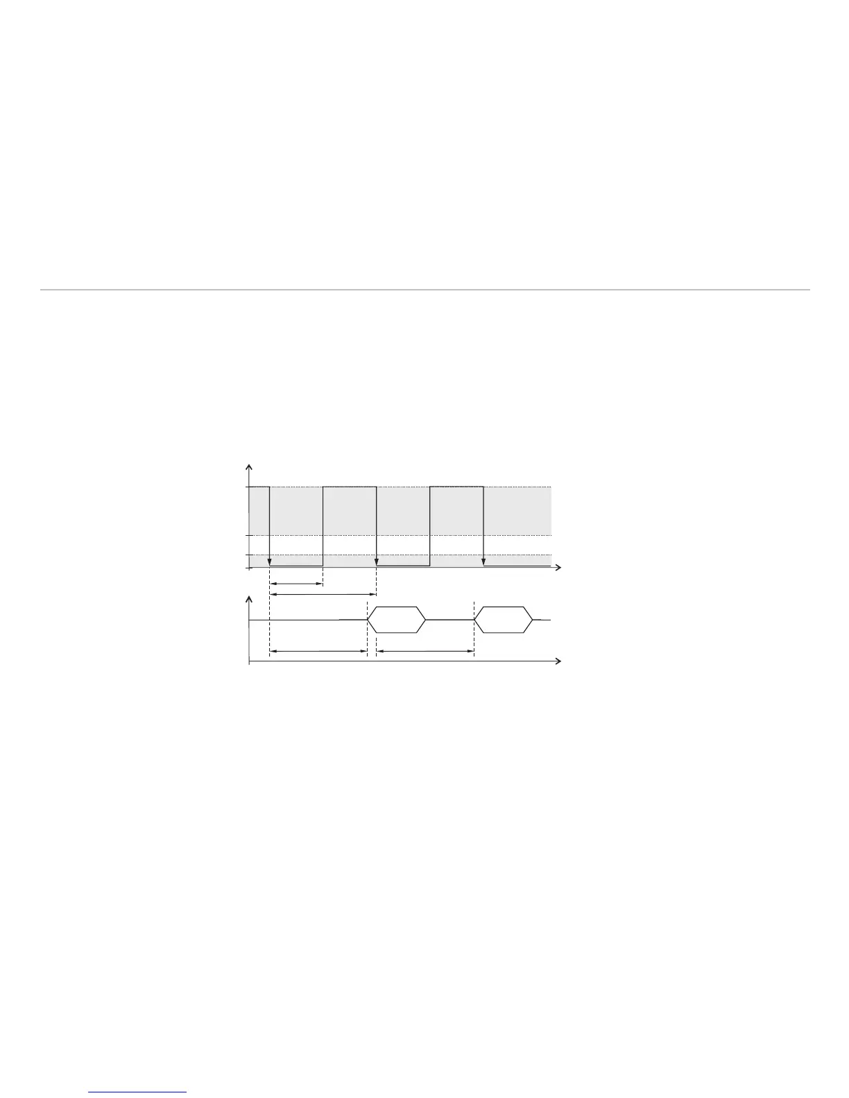
Basics, procedure:
The sensor measures and calculates also, if no trigger pulses are pending. -
The data output starts with a falling edge of the trigger signal. -
Sensor outputs the measurement value with a delay T -
T
of 1.4 up to 2 ms.
A new trigger pulse can be sent. -
t
N
Non-pulse period
t
I
Pulse interval
T
T
Delay time
T
T
= 1.4 … 2 ms
true for a measure-
ment rate of 1.5 kHz
and a baud rate of
115.200 Baud
Maximum trigger rate:
appr. 500 Hz
TimingFig. 15:
You get a digital measurement value on the output for each trigger signal, see data output Chap. 8.3.8 and
8.3.9. The analog output is actualized with any trigger signal, if you use the analog output.
i
An averaging of the measuring values has no effect on the delay time T
T
. Consider certainly, that the
controller needs time for the averaging, until measuring values are available according to the set avera-
ging number N.