Page 40
Serial Interface RS422
optoNCDT 1402
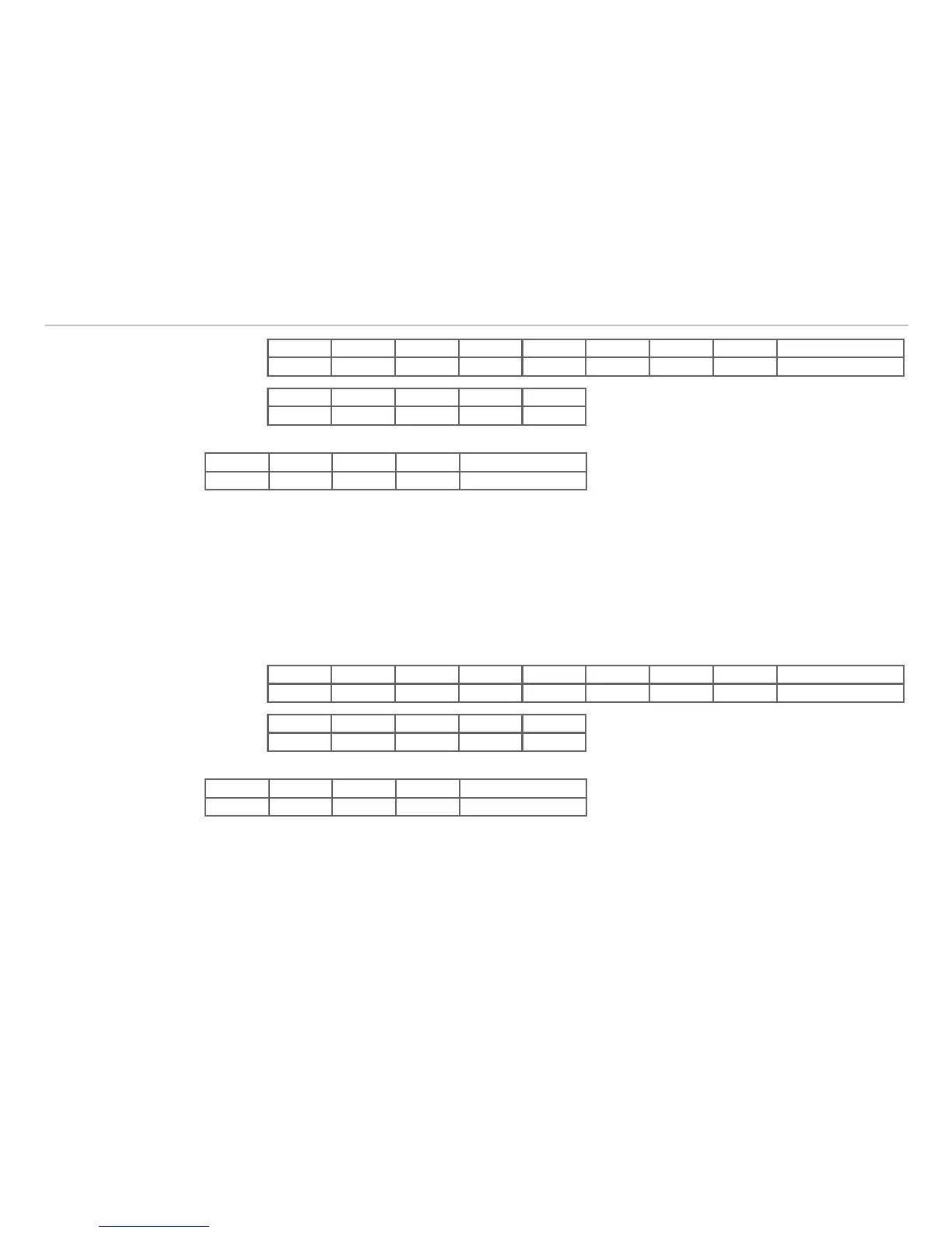
Format Byte 1 Byte 2 Byte 3 Byte 4 Byte 5 Byte 6 Byte 7 Byte 8 Byte 9
“+” “+” “+” 0x0D „I“ „L“ 0x10 0x01 Median ON/OFF
Reply Byte 1 Byte 2 Byte 3 Byte 4 Byte 5
„I“ „L“ 0x90 0x00 none
Command error-free
Byte 1 Byte 2 Byte 3 Byte 4 Byte 5
“I“ “L“ 0xD0 0x01 Error code
Faulty command
Digital or Analog Data Output8.2.6
Name: OUTPUTCHANNEL
Description: Selects the output channel (analog / digital) for the sensor. If the digital output is selected the
serial interface transmits measured values with a data rate of 1.5 kHz. If the analog output is selected the se-
rial interface transmits the commands and the responses only.
Byte 9 = 0; analog
Byte 9 = 1; digital
Format Byte 1 Byte 2 Byte 3 Byte 4 Byte 5 Byte 6 Byte 7 Byte 8 Byte 9
“+” “+” “+” 0x0D „I“ „L“ 0x0E 0x01 Channel
Reply Byte 1 Byte 2 Byte 3 Byte 4 Byte 5
„I“ „L“ 0x8E 0x00 none
Command error-free
Byte 1 Byte 2 Byte 3 Byte 4 Byte 5
“I“ “L“ 0xCE 0x01 Error code
Faulty command
Default setting:
analog output