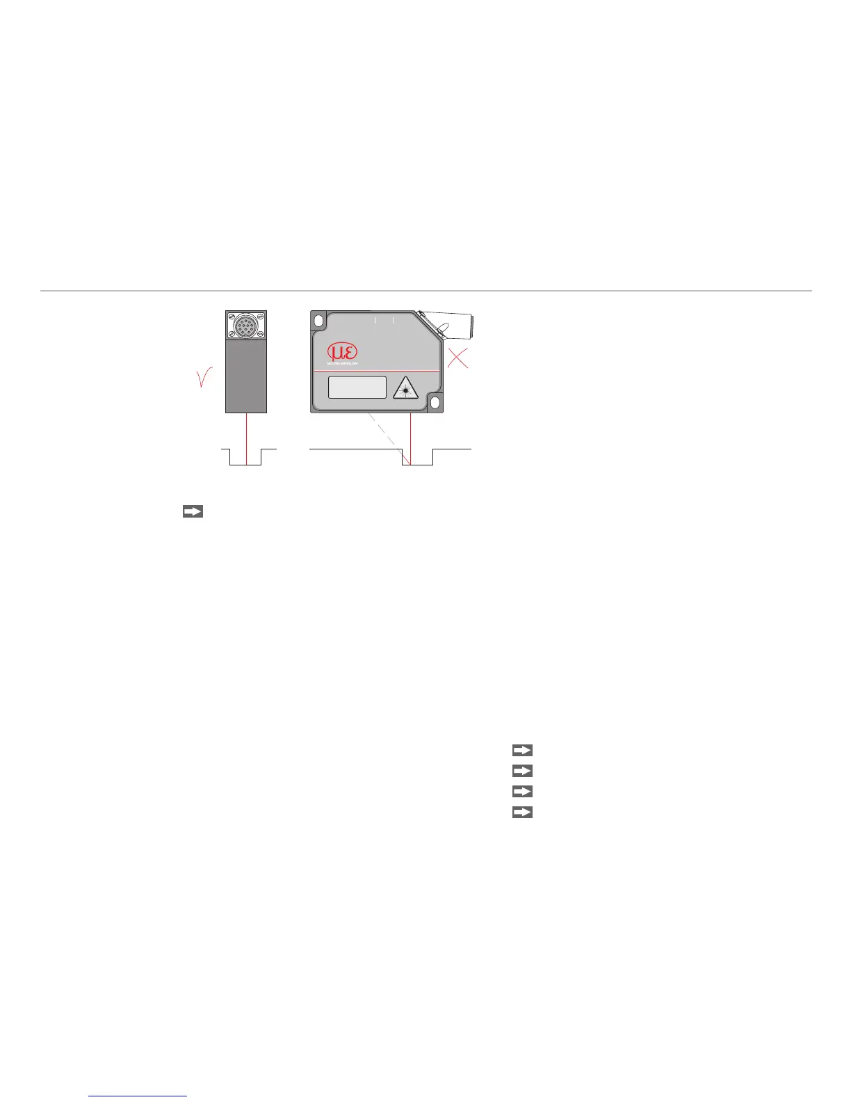
In case of bore holes, blind holes, and edges in
the surface of moving targets the sensor must
be arranged in such a way that the edges do not
obscure the laser spot (Fig. 24).
Sensor arrangement for holes and ridgesFig. 24:
Cleaning the Protective Glasses9.4
Clean the protective glass with high-percentage alcohol (propanol or optics cleaner) and a lint-free lens
cleaning paper or an optics cleaning cloth (from the optics or photo shop).
The surface is damaged if a dry cloth is used for cleaning.
Default Setting10.
Data protocol ILD1402 -
Current output with error value (3.75 mA) -
Measuring rate : 1.5 kHz -
Interface: 115.2 kBaud, binary format (no ASCII) -
Moving average avg =1 (no averaging) -
Teach value 1: 0.0 -
Teach value 2: 16368.0 -
External input for scaling -
Continuous measurement output -
Output time: 500 ms, -
Key lock after 5 min power on -
Settings saved into FLASH -
Measuring range: -
100 % FSO: I = 20 mA , digital 16207
0 % FSO: I = 4 mA, digital 161
Maximum output (101 % FSO): -
20.16 mA / digital 16367
Minimum output (-1 % FSO): -
3.84 mA / digital 0
Set sensor on default settings:
Switch off the senors power supply.
Keep the key “Select“ pressed.
Switch on the sensors power supply.
Wait about 5 sec.