Page 20
Installation and Mounting
optoNCDT 1402
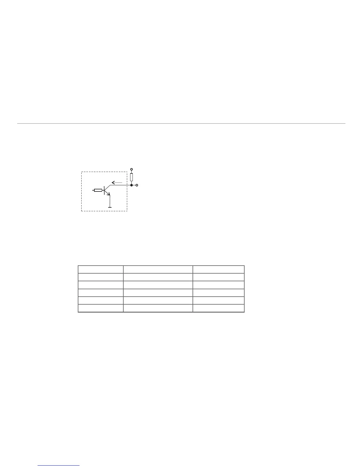
Error Output5.2.3
The error message is generated by:
no measuring object or measuring object beyond measuring range -
poor target (reflectivity to small, transparent or mirroring object) or laser off -
U
CE max.
= 30 VDC
No error: T locked
Error: T conductive
The error output is low-active and short circuit proof.
External wiring for the error output Fig. 7:
i
With a user defined output scaling, see Chap. 6.2, you can use the hysteresis-free error output as a
programmable limit switch.
Pin Assignment for RS422 Interface5.3
The lines have to be crossed for the connection between sensor and PC.
Sensor Terminal (USB converter) Colors PC1402-x/I
Tx+ (Pin 5) Rx+ (Pin 9) grey
Tx - (Pin 6) Rx - (Pin 1) pink
Rx+ (Pin 3) Tx+ (Pin 2) green
Rx - (Pin 4) Tx - (Pin 3) yellow
GND (Pin 12) GND (Pin 5) blue
i
Disconnect or connect the D-sub connection between RS422 and USB converter when the sensor is
disconnected from power supply only.