Page 18
Installation and Mounting
optoNCDT 1402
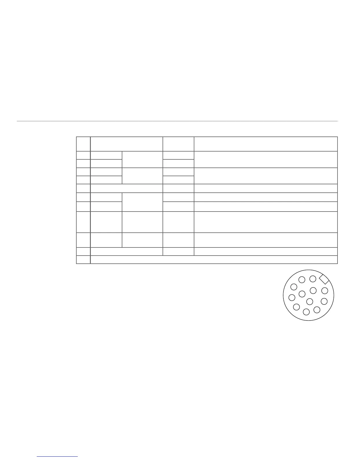
Pin Assignment5.2
Pin Description
Color code
PC1402-x/I
Specification
3 RS422 Rx+
Serial input
green
Internally terminated with 120 Ohm
4 RS422 Rx- yellow
5 RS422 Tx+
Serial output
grey
Terminate externally with 120 Ohm
6 RS422 Tx- pink
7 +U
B
red 11 ... 30 VDC, typical 24 VDC / 50 mA
8 Laser off
Switch input
black Laser is active, if pin 8 is connected with GND
9 Teach in violet Connected to GND for at least 30 ms
10 Error Switch output brown
Open-Collector (NPN), I
max
= 100 mA, U
max
= 30 VDC,
short circuit proof, turn off the power supply to reset the
short circuit protection
11 I
OUT
4 ... 20 mA white
R
Load
< (U
B
- 6 V) / 20 mA; R
Load
max. = 250 Ohm with
U
B
= 11 V
12 GND blue Supply and signal ground
1/2 n.c.
The shield of the cable is connected with the housing of the connector. The sup-
ply and output cable PC1402-x/I is a high flex cable.
One end of the cable has a molded M12 female connector, the other end has
free leads with ferrules.
Pin side male cable connectorFig. 5: