Page 19
Installation and Mounting
optoNCDT 1402
Switching off the Laser5.2.1
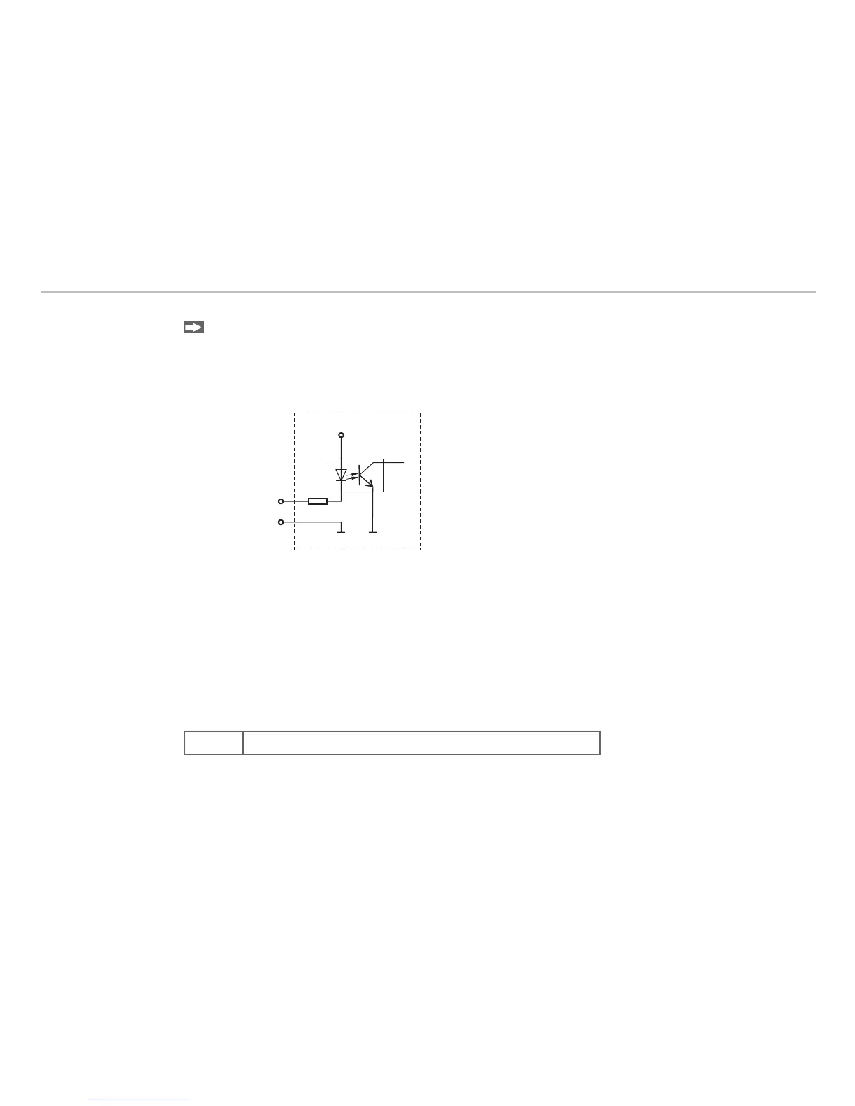
Connect pin 8 with pin 12 to switch on the laser.
If you open this connection
the laser switches off, -
the error output switches on, -
the “State“ LED switches off. -
Circuit for laser off, analog scaling and trigger inputFig. 6:
Input for Analog Scaling and Triggering5.2.2
If pin 9, see Fig. 6, is selected as input to scale the analog output in the sensor configuration (Chap. 8.3.14)
and if pin 9 is connected with pin 12 more than 2 sec, the scaling of the analog output starts, see Chap. 6.2.
The minimum pulse duration is 30 ms, see Fig. 11.
This external input can be configured as a trigger input to output the measurements also. If pin 9 is con-
nected with pin 12 measurements are output at the serial or analog output. The maximum trigger frequency is
500 Hz.
Trigger conditions:
Wiring connect with ground, e.g. a relay or open-collector (NPN)