The process interface has an integrated fail-safe mode. This allows to control conditions like interruption of
cables, shut-down of the software etc. and to give out these conditions as an alarm.
Controlled conditions on camera
and software
Standard Process interface
TM-PIF-TIM
Industrial Process interface
TM-PIF500V2C5-TIM
Controlled USB cable to camera
Interruption data cable camera -
PIF
Interruption power supply - PIF
Shut-down of TIMConnect
software
Crash of TIMConnect software -
Fail-Safe output 0V at analog output (AO) Open contact (fail-safe-relay) / red
LED on
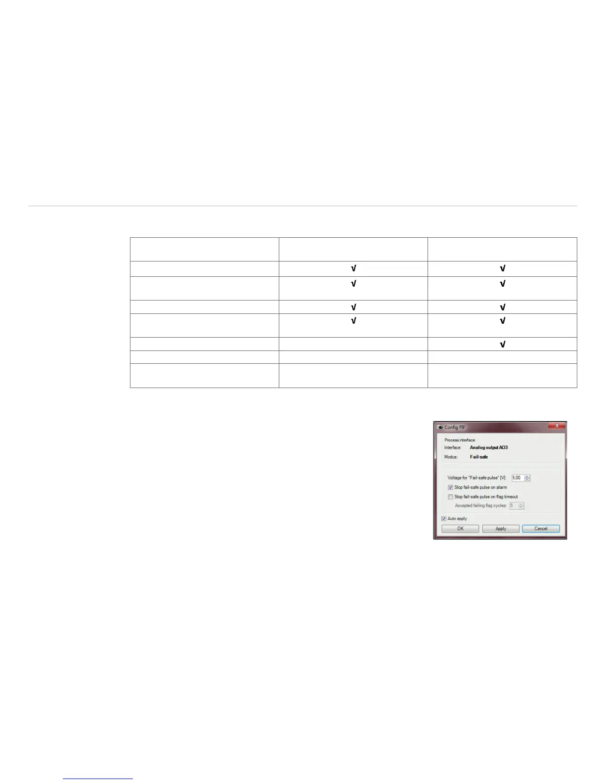
The failsafe function can be activated in the tab Device (PIF) under FS. The industrial PIF has a separate
failsafe relay.
Alternatively you can activate this function also on the analog out-
puts. The checkbox Stop fail-safe pulse on alarm must be
activated, if the analog output should be used in addition as an alarm
output for a temperature alarm. In case of an alarm the alternating
fail-safe pulse signal will stop and the set voltage level will be given
out as constant value (Industrial PIF only).