5-22 Image Optimization
Map
Description This feature indicates the display effect of power image. The maps in
Power mode image are grouped into two categories: Power maps and
Directional Power maps.
Operation Select the map through the [Map] item in the soft menu or menu.
There are 8 kinds of maps provided: P0-3 belong to Power Mode maps,
while dP0-3 belong to Directional Power Mode maps.
The Power maps provide information of blood flow, which are highly
sensitive to the low-velocity flows.
The Directional Power maps provide information of flow direction.
Impacts The function is available in real-time imaging, freeze or cine review status.
Dynamic Range
Description This function is to adjust the transformation of echo intensity into color
signal.
Operation Adjust through the [Dyn Ra.] item in the soft menu or menu.
The adjusting range is 10-70dB in increments of 5dB.
Effects Increasing dynamic range will lead to higher sensitivity to low-power
signals, thus enhances the range of signals to display.
5.7 PW/CW Doppler Mode Optimization
PW (Pulsed Wave Doppler) mode or CW (Continuous Wave Doppler) mode is used to
provide blood flow velocity and direction utilizing a real-time spectral display. The
horizontal axis represents time, while the vertical axis represents Doppler frequency shift.
PW mode provides a function to examine flow at one specific site for its velocity, direction
and features; while CW mode proves to be much more sensitive to high velocity flow
display. Thus, a combination of both modes will contribute to a much more accurate
analysis.
5.7.1 PW / CW Mode Exam Protocol
1. Select a high-quality image during B mode or B+ Color (Power) scanning, and adjust
to place the area of interest in the center of the image.
2. Press <PW>/<CW> to enter the sampling state,
z The sampling parameters will be displayed in the image parameter area on the
left part of the screen as follows:
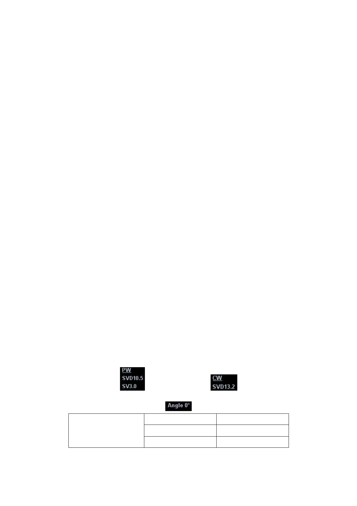
z
The sampling correction angle value will be displayed above the image, as
described in the following table:
PW Sampling Line
Adjustment
SV Size SV 3.0
Angle
Angle 0°
SVD SVD 10.5cm